
Parameter display controller for an acoustic signal processing apparatus

a display controller and acoustic signal technology, applied in the field of acoustic signal processing apparatus, can solve the problems of difficult to quickly recognize the ordinal position of the channel group, difficult to perceive the ordinal position of the currently illuminated led indicator among all led indicators, and inconvenient conventional methods, etc., to achieve quick, reliable and easy recognition

Inactive Publication Date: 2011-08-23
YAMAHA CORP
View PDF10 Cites 25 Cited by
  • Summary
  • Abstract
  • Description
  • Claims
  • Application Information

AI Technical Summary

Benefits of technology

[0006]The present invention was accomplished to solve the above-described inconvenience, and an object thereof is to provide quick, reliable and easy recognition of the currently setting-established part in the entire parameter-establishable range of the parameter display portion displaying a parameter setting by use of a plurality of display elements.
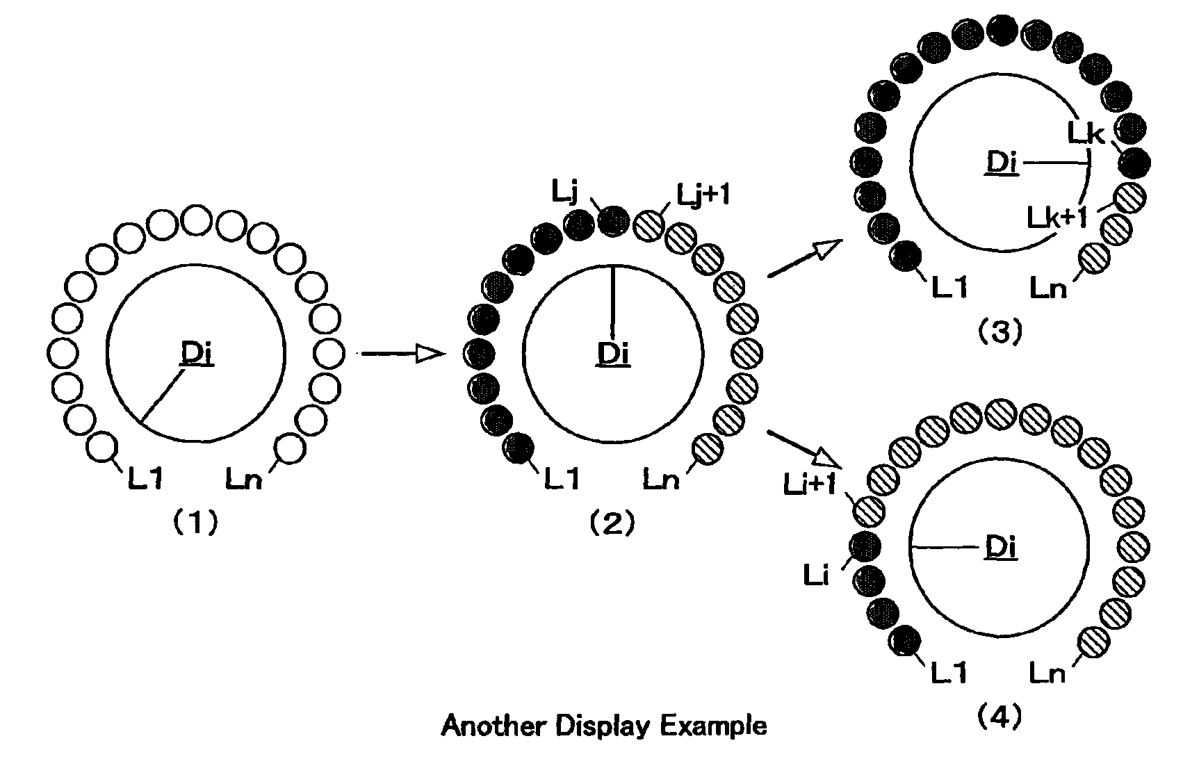
[0011]According to the present invention, the parameter display portion is adapted to display a value of a parameter by use of a plurality of display elements during operation of the apparatus. A part of the display elements is energized in a first display mode, while the remaining display elements are energized in a second display mode. As a result, since all the display elements are displayed in either of the two modes, the present invention produces a unique effect of providing easy perception of the entire parameter-settable range while also providing quick, reliable and easy recognition of the part where a value of a parameter has been set within the entire range through the use of the display elements in the first display mode. In addition, the light-emitting display elements exert a remarkable effect when the apparatus is used, particularly, in dark conditions.

Problems solved by technology

In the conventional display manner, however, it is difficult to perceive the ordinal position of the currently illuminated LED indicator among all the LED indicators because only the LED indicator for a channel group to which a channel is assigned is lit up while the LED indicators for other channel groups are extinguished.
As a result, it is impossible to quickly recognize the ordinal position of the channel group to which the channel is assigned.
Particularly, the conventional manner is notably inconvenient when the apparatus is used in the dark.

Method used


Image

  • Parameter display controller for an acoustic signal processing apparatus
  • Parameter display controller for an acoustic signal processing apparatus
  • Parameter display controller for an acoustic signal processing apparatus

Examples


Embodiment Construction

[0018][Hardware Configuration]

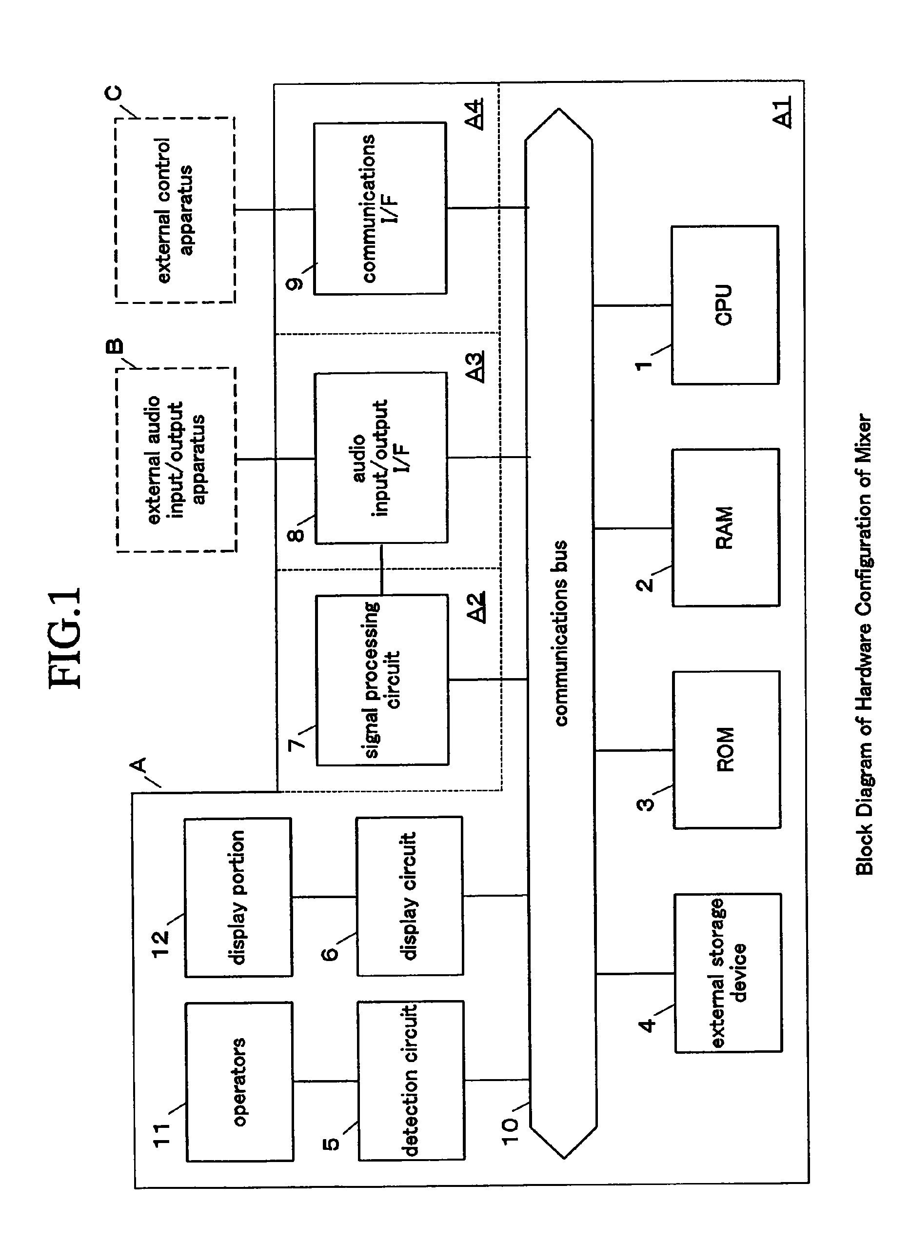
[0019]FIG. 1 shows a block diagram illustrating a hardware configuration of a digital audio mixer to which parameter display control according to an embodiment of the present invention is applied. In FIG. 1 a digital audio mixer A has a central processing unit (CPU) 1, random access memory (RAM) 2, read-only memory (ROM) 3, external storage device 4, detection circuit 5, display circuit 6, signal processing circuit 7, audio input / output interface (I / F) 8, communications interface (I / F) 9, etc. These devices 1 through 9 are interconnected via a communications bus 10.

[0020]The CPU 1, RAM 2, ROM 3, external storage device 4, detection circuit 5 and display circuit 6 along with an operator device 11 connected to the detection circuit 5 and a display portion 12 connected to the display circuit 6 form a control section Al of the mixer A. The CPU 1 controls the whole of the mixer A in accordance with specified software programs. For example, the CPU 1 controls...


PUM


Abstract

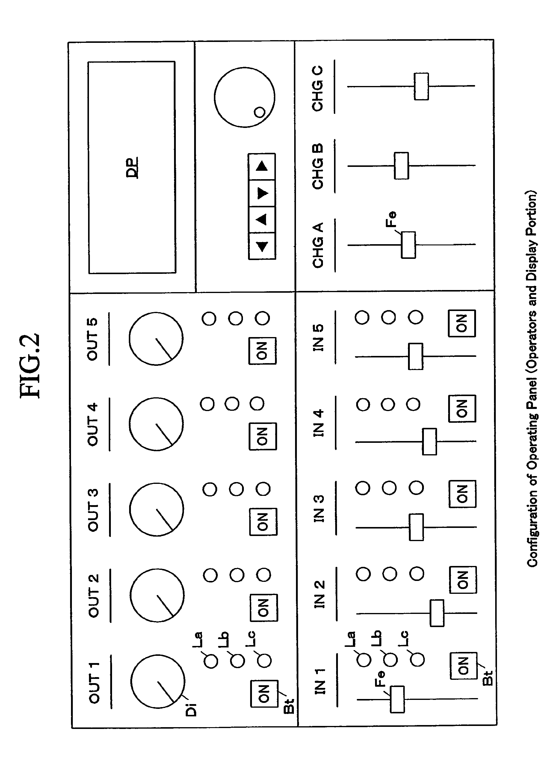
A parameter display portion of an acoustic signal processing apparatus (mixer) according to the present invention displays a setting of a parameter (channel group setting parameter) by use of a plurality of light-emitting display elements (LED) La through Lc. While the acoustic signal processing apparatus is under operating conditions with a setting of the parameter being established through a setting operation of an operator (on-switch) Bt, the display elements La through Lc in the entire parameter-establishable range are kept in display action. The parameter display portion is controlled such that, during the display action, the display element [(2)=La, (3)=Lb, (4)=Lc] corresponding to the established setting is displayed in the first display mode, while the other display elements [(2)=Lb and Lc, (3)=La and Lc, (4)=La and Lb] excluded from the established setting being displayed in the second display mode. As a result, the present invention provides quick, reliable and easy perception of the currently setting-established part in the entire parameter-establishable range.

Description

BACKGROUND OF THE INVENTION[0001]1. Field of the Invention[0002]The present invention is applied to an acoustic signal processing apparatus such as a digital audio mixer. In particular, the present invention relates to a parameter display controller and a parameter display computer program for controlling a parameter display portion displaying parameters indicative of operational settings by use of a plurality of display elements.[0003]2. Description of the Related Art[0004]Conventionally, there have been musical acoustic signal processing apparatuses such as digital audio mixers having a display panel in which input channel or output channel operators are provided with LED indicators indicative of the status of channel group assignment. Each channel operator has the LED indicators of a number equal to the number of channel groups in the vicinity thereof in order to turn on an LED indicator corresponding to a channel group to which the channel operator is currently assigned and turn...

Claims


Application Information

Patent Timeline
IPC IPC(8): H04B1/00H04R3/00G09G3/00H04R3/14
CPCH04H60/04G10H2220/026
Inventor TERADA, KOTAROOTA, MITSUHIKO
Owner YAMAHA CORP
Learn More