Active brake pulsation control

a brake pulsation and control technology, applied in the field of control systems, can solve the problems of normal brake pulsation feedback and noise, fluctuation in brake torque, and customer dissatisfaction, and achieve the effect of minimizing brake pulsation feedback

Inactive Publication Date: 2011-08-16
GM GLOBAL TECH OPERATIONS LLC
View PDF43 Cites 3 Cited by
  • Summary
  • Abstract
  • Description
  • Claims
  • Application Information

AI Technical Summary

Benefits of technology

[0008]A brake system is provided for minimizing brake pulsation feedback caused by surface variations of a brake system corner component such as a brake rotor or drum. The brake system includes at least one sensing device configured to measure a pressure pulse caused by the surface variation of the brake system corner component.
[0009]A controller module is in communication with the at least one sensing device and a hydraulic brake circuit. The controller module is configured to increase or decrease line pressure in the hydraulic brake circuit by an amount that is equal in magnitude and out-of-phase with the pressure pulse caused by the surface variation of the brake system corner component to substantially minimize brake pulsation feedback.

Problems solved by technology

Both RTV and DRV are frequently the result of variations in machining procedures but can also be caused by uneven wear of brake pads or shoes, corrosion, loose brake parts and / or uneven thermal expansion of brake corner components.
The fluctuation in brake torque can also be a result of a non-uniform friction or frictional variations on the braking surface (non-uniform transfer film on the braking surface).
If the vehicle is equipped with an Anti-Lock Brake System (ABS), however, brake pulsation feedback and noise are normal during panic stops or when braking on wet or slick surfaces.
In either case, brake pulsation feedback can be annoying to the driver of the vehicle, resulting in customer dissatisfaction and increased warranty claims.
Additionally, efforts to eliminate brake pulsation feedback may be costly and time consuming, ranging from having to “turn” the rotors and / or drums to smooth the surfaces thereof, to having these components replaced altogether with the brake pads and shoes.

Method used


Image

  • Active brake pulsation control
  • Active brake pulsation control
  • Active brake pulsation control

Examples


Embodiment Construction

[0019]The following detailed description is merely exemplary in nature and is not intended to limit the invention or the application and uses of the invention. Furthermore, there is no intention to be bound by any expressed or implied theory presented in the preceding technical field, background, brief summary or the following detailed description.

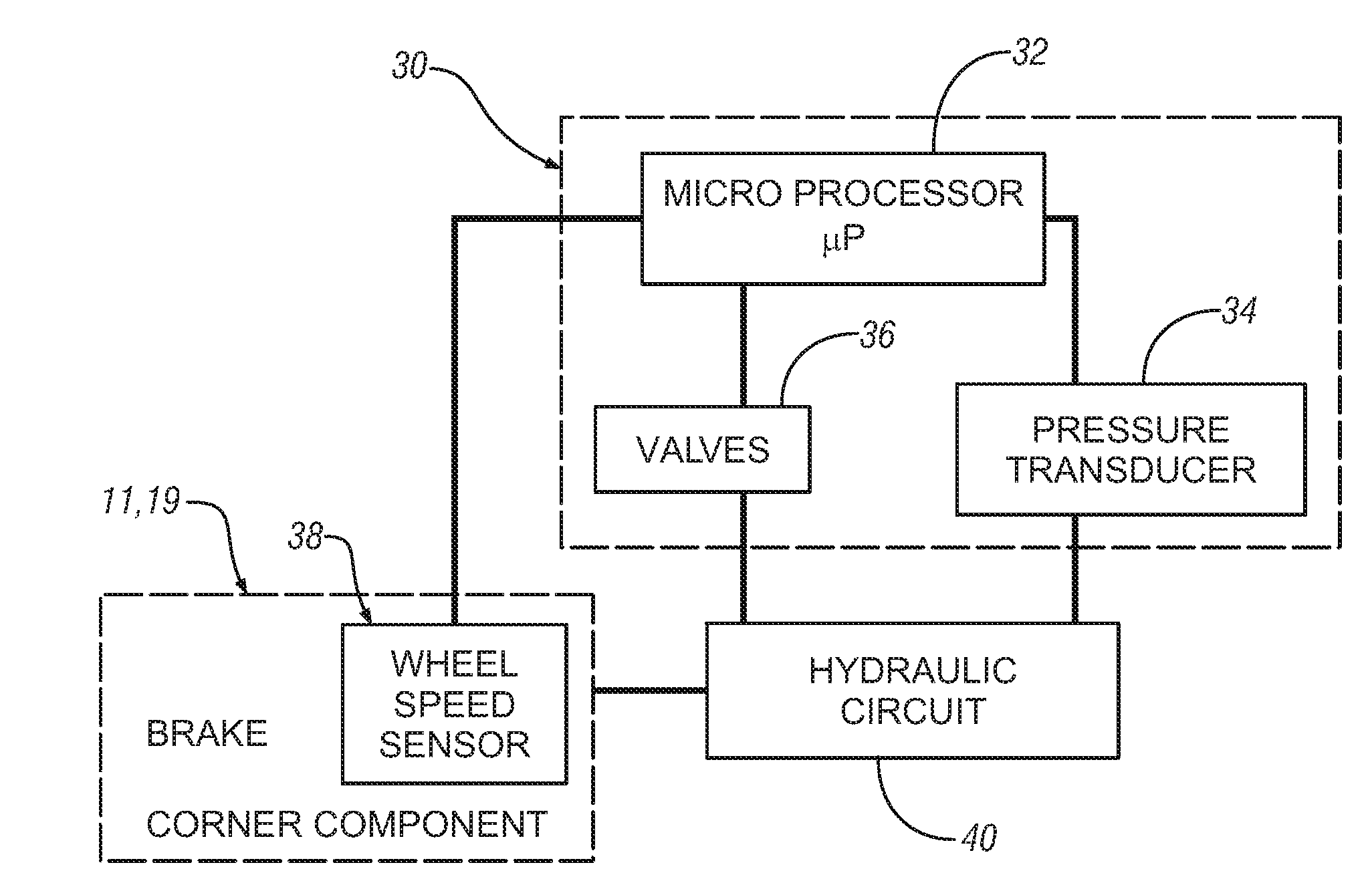
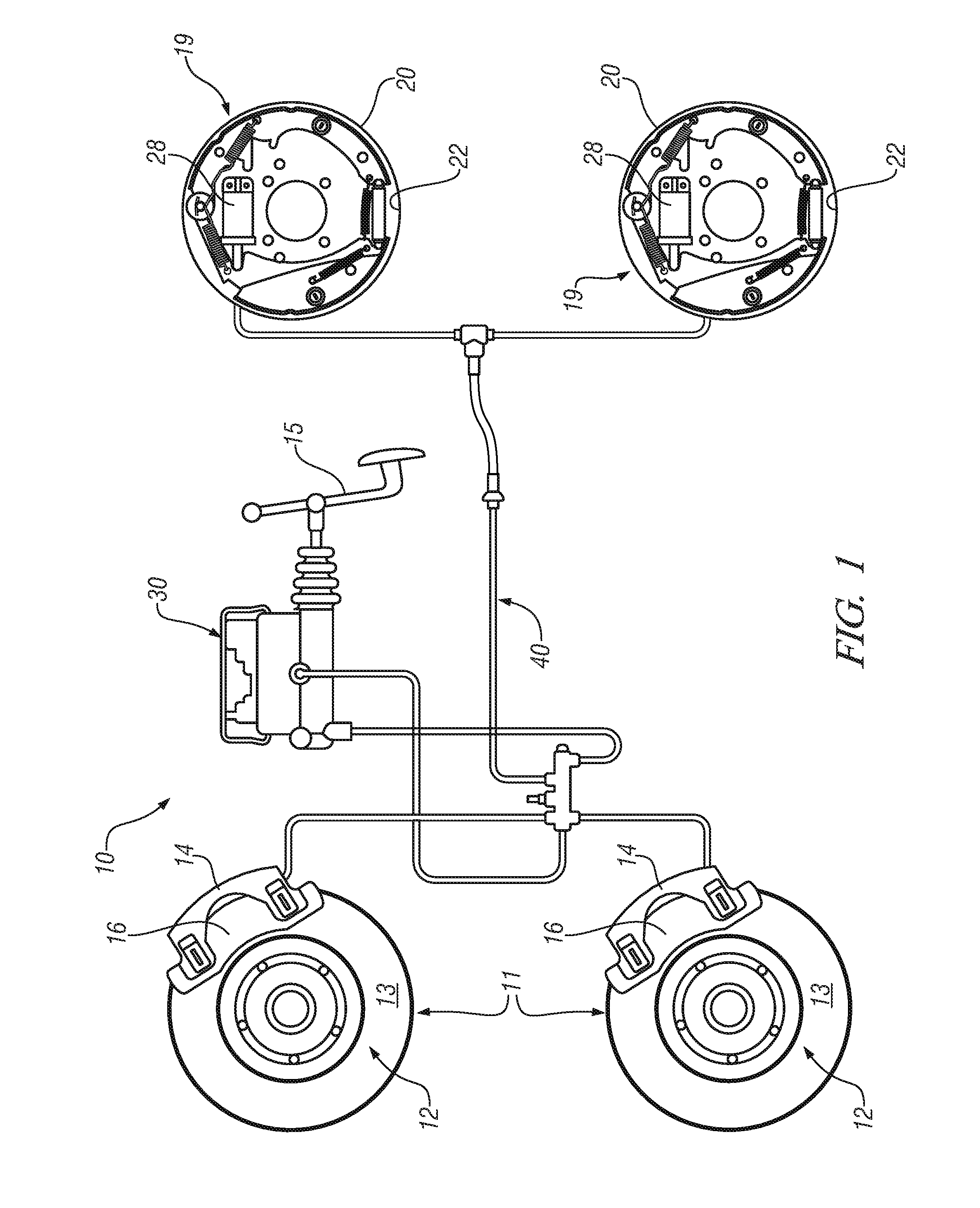
[0020]FIG. 1 is a perspective view of an exemplary vehicle braking system 10 for minimizing brake pulsation feedback caused by a surface variation of a braking system corner component. The braking system 10 includes disc brake corner components 11 and brake shoe corner components 19.

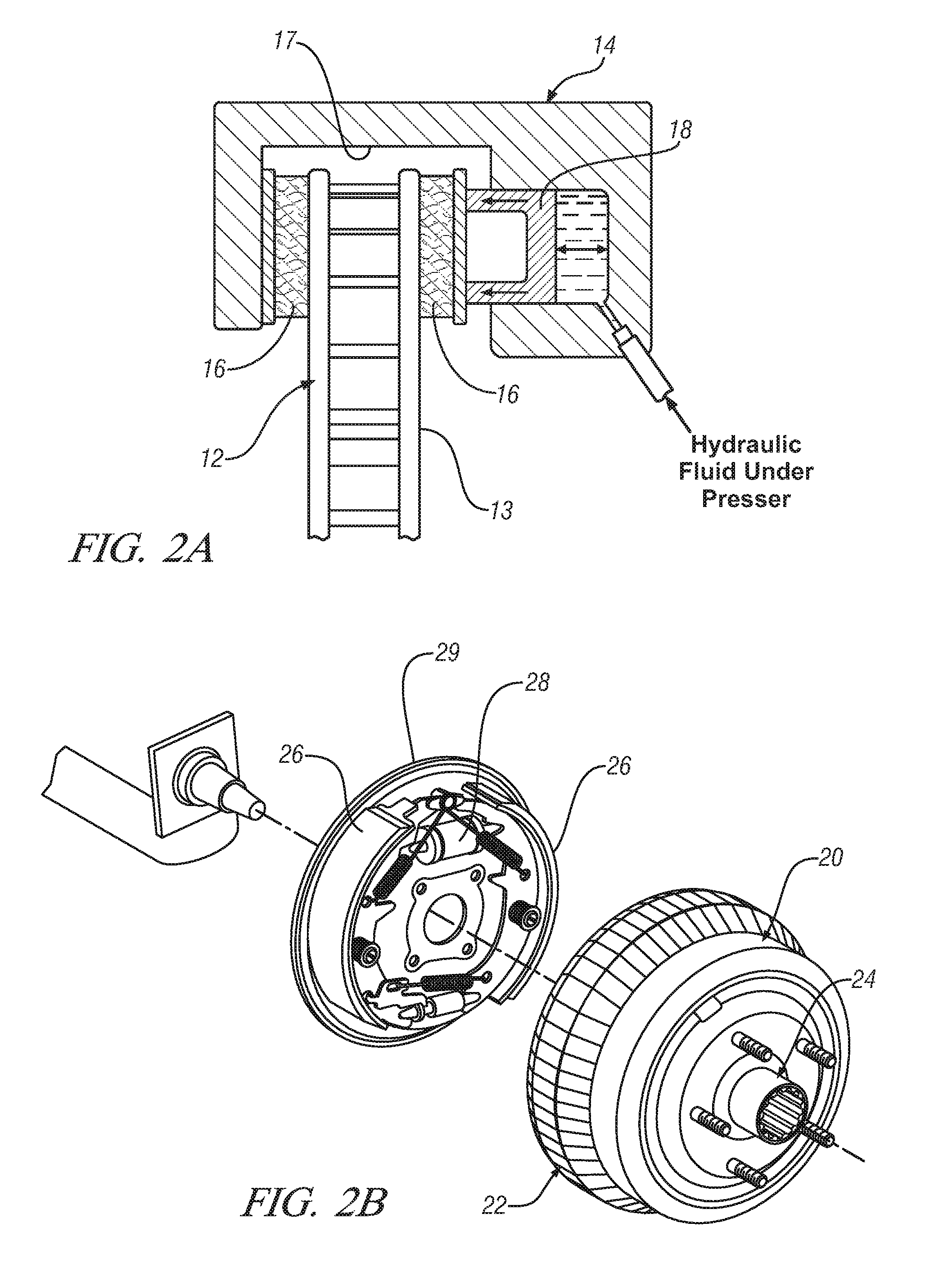
[0021]The disc brake corner components 11 include a rotor 12, a brake caliper 14, brake pads 16 and a wheel speed sensor 38 (see FIG. 3). The rotor 12 is a plate-like component that attaches to the wheel of the vehicle and includes opposing planar contact surfaces 13 (see FIG. 2A). The brake caliper 14 is a generally U-shaped device that includes a longitudinal...


PUM


Abstract

A brake system is provided for minimizing brake pulsation feedback caused by surface variations of a brake system corner component. The brake system includes at least one sensing device configured to measure a pressure pulse caused by the surface variation of a brake system corner component. A controller module is in communication with the at least one sensing device and a hydraulic brake circuit. The controller module is configured to receive an output from the at least one sensing device and to adjust line pressure in the hydraulic brake circuit to substantially minimize brake pulsation feedback.

Description

TECHNICAL FIELD[0001]The present invention generally relates to control systems installed in automobiles and other vehicles, and more particularly relates to methods and systems for controlling brake line pressure to minimize tactile feedback caused by surface variations of a brake system corner component.BACKGROUND OF THE INVENTION[0002]Brake systems for most modern vehicles consist of disc brakes, drum brakes or a combination of the two systems. An example of a disc brake system is a single-piston floating caliper (SPFC) system. The main brake corner components of a SPFC disc brake system are the brake pads, the caliper, the rotor, and the hydraulic brake circuit. The rotor is a plate-like disc that is configured to attach to, and rotates with, the hub of the vehicle wheel. The caliper is mounted adjacent the peripheral edge of the rotor and houses the brake pads and a single piston that is actuated by hydraulic pressure via the hydraulic brake circuit. When the brake pedal is pus...

Claims


Application Information

Patent Timeline
Patent Type & Authority Patents(United States)
IPC IPC(8): B60T7/00
CPCB60T8/00B60T8/48B60T17/221F16D65/0006F16D66/00F16D2066/005
Inventor DESSOUKI, OMAR S.LOWE, BRENT D.RIEFE, MARK T.
Owner GM GLOBAL TECH OPERATIONS LLC
Why Eureka
Try Eureka