Missile launching system, and a hanger member for suspending the missile in a launch rail

a missile and launch system technology, applied in the field of missile launching system, can solve the problems of reducing the safe transportation time of missiles carried by aircraft, power boost in the rear part which could be seriously damaged, and missiles are not permitted to let their rear parts, so as to prevent, or at least minimize, the risk of the rearmost section

Inactive Publication Date: 2011-08-16
SAAB AB
View PDF18 Cites 7 Cited by
  • Summary
  • Abstract
  • Description
  • Claims
  • Application Information

AI Technical Summary

Benefits of technology

[0006]It is a primary object of the present invention to provide an improved structure of the rearmost hanger which eliminates the above-mentioned drawbacks of earlier proposals and which is capable of taking up both compressive forces and tensile forces acting on the missile during flights, while during launch of the missile being able to separate the part of the hanger that takes up the tensile loads. For this purpose the missile launch system of the kind mentioned in the introduction is characterized in that the rearmost hanger includes two separable main parts, i.e. a first main part for engagement with a respective lateral, first groove section of the T-slot, and a second main part configured to be attached to the missile and be slidably guided in a second groove section of the T-slot normal to the first groove section and opening towards the missile, said second main part having laterally extending collars configured to interact in close proximity with respective rail sections facing the missile. When launching the missile, the second main part is adapted to separate from the first part, which remains left on the launch rail, so that the missile may freely leave the launch rail as the foremost hangers have disengaged from their grooves in the rail, thereby minimizing the risk for an undesired contact between the rearmost section of the missile and the launch rail.
[0007]According to a suitable embodiment of the system of the invention the first and second main parts of the rearmost hanger are mutually detachably connected by a longitudinally extending dovetail joint. This will allow for a smooth separation of the hanger parts.
[0008]It is another object of the present invention to provide a hanger member for attachment to a rear section of a missile for suspending and guiding the missile in a longitudinal slot of a launch rail. The hanger member allows for a smooth separation of two hanger main parts and to prevent, or at least minimize, the risk for the rearmost section of the missile to come into contact with the launch rail during launch.

Problems solved by technology

However, some types of missiles are not permitted to let their rear parts come into contact with the launch rail for safety reasons.
For example, this is true for missiles equipped with a sensitive power boost in their rear part which could be seriously damaged if contacting the rail too hard during launch.
Since this modified rear hanger is not capable of taking up tensile forces during normal flight time, due to the fact that this rear hanger lacks lateral flanges engaging side grooves in the launch rail, the hangers located in front thereof will be subjected to higher tensile loads which affects the durability and the allowed overall load applied to the missile, thereby reducing the safe transportation time for the missiles carried by an aircraft.
A reason why the lateral flanges of the rearmost hanger, which take up tensile forces during the flight of the aircraft, are not suitable during missile launch, is that these lateral flanges tend to create an undesired hinge action at the rear hanger when the foremost hangers have been disengaged from their slots in the launch rail and the missile tends to dive, thereby causing the rearmost part of the missile to move upwardly and possibly hit the launch rail.
Also, such a rear hanger may cause a jam problem while sliding in the corresponding tracks of the launch rail and cause a greater air resistance of the missile.

Method used


Image

  • Missile launching system, and a hanger member for suspending the missile in a launch rail
  • Missile launching system, and a hanger member for suspending the missile in a launch rail
  • Missile launching system, and a hanger member for suspending the missile in a launch rail

Examples


Embodiment Construction

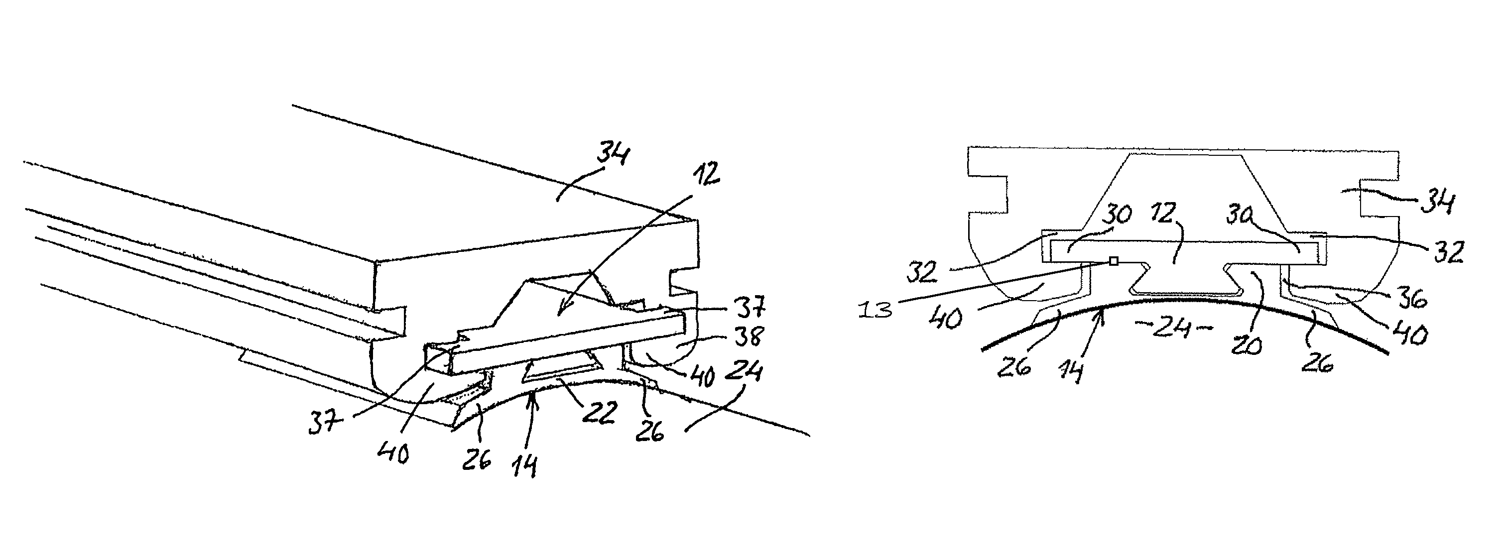
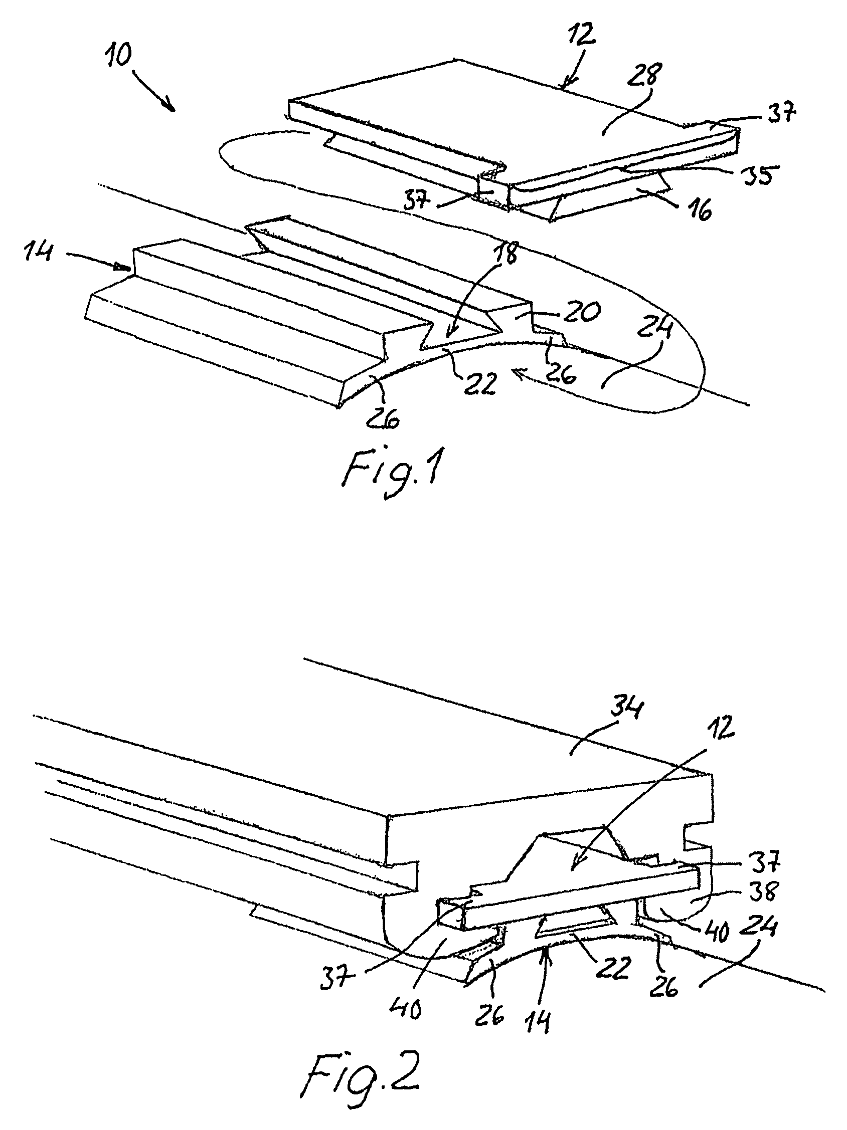
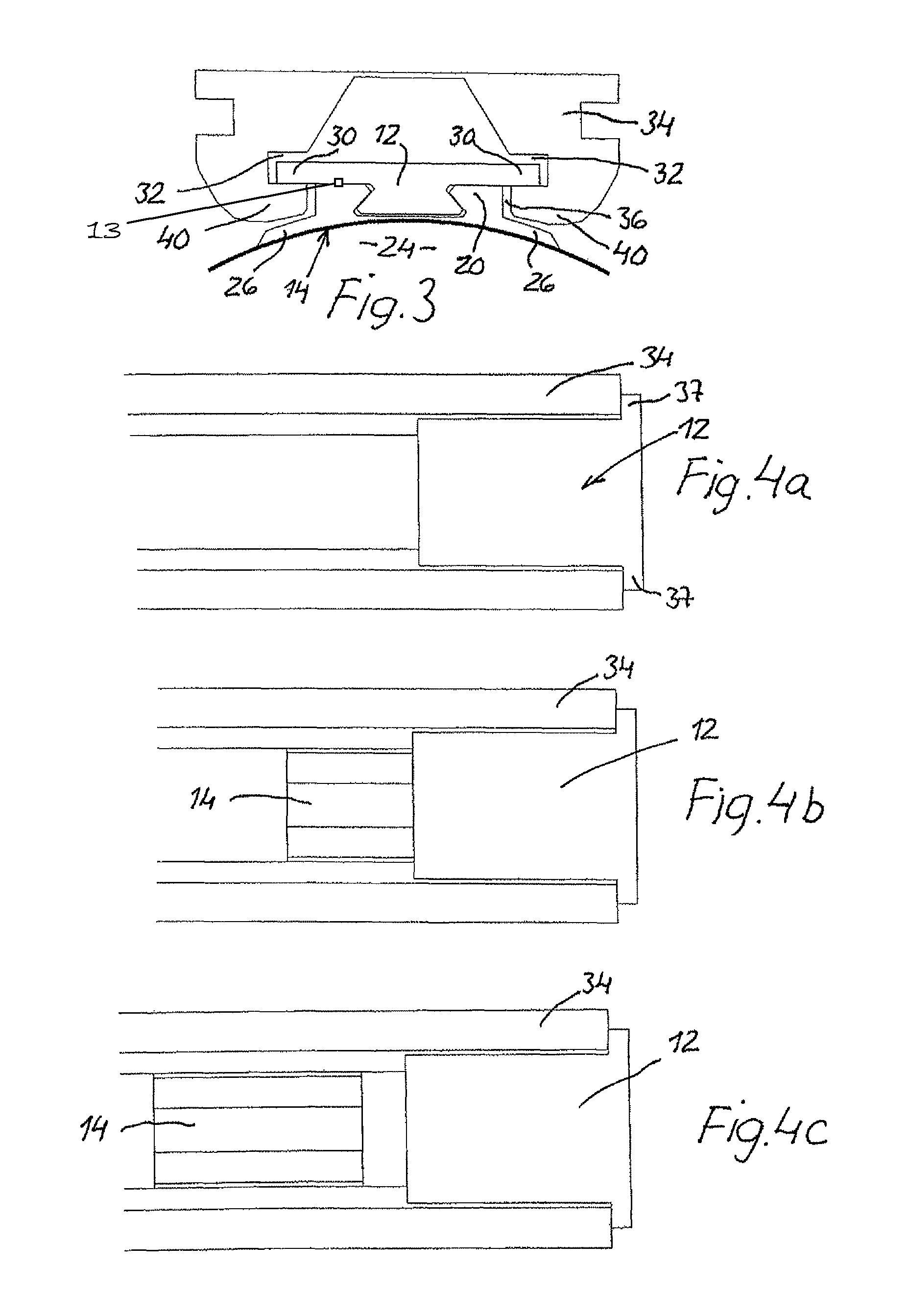
[0013]FIG. 1 illustrates a rearmost hanger member 10 of an aircraft missile launch system of the invention in a disassembled condition. The hanger member 10 includes an upper main part 12 and a lower main part 14, which are mutually slidably connected by means of a longitudinally extending dovetail joint formed by a rib element 16 of a trapezoidal profile of the upper main part 12, and a correspondingly shaped groove 18 in a web portion 20 of the lower main part 14. Of course, other configurations of a longitudinal, separable joint between the parts 12, 14 are conceivable, such as a T-shaped joint or the like. The upper and lower parts 12, 14 may be detachably fixated to one another by any suitable locking means 13, such as a spring-loaded ball in one part which snaps into a corresponding recess in the other part. The locking force of these locking means are easily overcome when launching the missile. There are also provided any conventional, releasable snubbing mechanisms (not show...


PUM


Abstract

A missile launching system including a launch rail for attachment to an aircraft and having a longitudinal slot, and at least two hangers for attachment to the missile at longitudinally spaced locations thereof and having a cross-section configured to be received in the longitudinal slot in the launch rail. The rearmost hanger includes two separable main parts, including a first main part for engagement with a respective lateral, first groove section of the slot, and a second main part configured to be attached to the missile and be slidably guided in a second groove section of the slot normal to the first groove section and opening towards the missile. The second main part includes laterally extending collars configured to interact in close proximity with respective rail sections facing the missile. The second main part is configured to separate from the first part when launching the missile.

Description

CROSS-REFERENCE TO RELATED APPLICATIONS[0001]This application claims priority to European patent application 08102336.8 filed 6 Mar. 2007.BACKGROUND OF THE INVENTION[0002]The present invention relates to a missile launching system, comprising a launch rail for attachment to an aircraft and having a substantially T-shaped longitudinal slot, and at least two hanger members for attachment to the missile at longitudinally spaced locations thereof, at least the rearmost hanger member of which having a substantially T-shaped section configured to be received in the longitudinal T-slot in the launch rail.[0003]The invention also relates to a hanger member for attachment to a rear section of a missile for suspending and guiding the missile in a longitudinal slot of a launch rail.[0004]Missiles carried by and launched from an aircraft are usually slidably suspended in one or more longitudinally extending slots of a launch rail by means of so-called hangers attached to the top side the missil...

Claims


Application Information

Patent Timeline
Patent Type & Authority Patents(United States)
IPC IPC(8): F41F3/06B64D1/04
CPCB64D7/08F41F3/0406
Inventor SODERBERG, HANS
Owner SAAB AB
Why Eureka
Try Eureka