
Power supply device for vehicles

a technology for power supply devices and vehicles, which is applied in the direction of motor/generator/converter stoppers, battery/fuel cell control arrangements, dynamo-electric converter control, etc., and can solve the problems of reduced travel performance of electric vehicles, reduced current at the time of recovering the regenerative power of motors into secondary batteries, and reduced current at the time of regenerative power of motors

Inactive Publication Date: 2011-08-09
HONDA MOTOR CO LTD
View PDF8 Cites 11 Cited by
  • Summary
  • Abstract
  • Description
  • Claims
  • Application Information

AI Technical Summary

Benefits of technology

[0009]The present invention has been accomplished in view of the aforementioned problems, and an object of the invention is to provide a power supply device for vehicles, which can prevent defects caused by limiting input and output currents of a secondary battery, thereby reducing the deterioration of the secondary battery.
[0012]In the power supply device for vehicles, during the power running operation of the motor, the current control means limits the current, which is output from the secondary battery to the motor, to at most the discharge limit current. During the regenerative operation of the motor, the current control means limits the current, which is input to the secondary battery from the motor, to at most the charge limit current smaller than the discharge limit current. Accordingly, during the power running operation of the motor, it is possible to prevent the insufficient power supply from secondary battery to the motor. Further, during the regenerative operation of the motor, it is possible to prevent an increase in inter-terminal voltage of the secondary battery caused by the internal resistance of the secondary battery which increases as the charging current increases.
[0013]Further, as the inter-terminal voltage of the secondary battery when the secondary battery is charged is prevented from increasing, the secondary battery can be substantially fully charged while being prevented from being deteriorated due to overcharge. Accordingly, since the output of the secondary battery can be increased during the power running operation of the motor, power which needs to be output from the capacitor can be reduced as much as the increase of the output of the secondary battery, which makes it possible to reduce the capacity of the capacitor. Further, when the input current of the secondary battery is reduced, an input current at the time of recovering the regenerative power of the motor through secondary battery decreases, but the regenerative power can be recovered into the capacitor connected in parallel to the secondary battery, which makes it possible to effectively use the regenerative power of the motor without loss.
[0014]The power supply device further includes a temperature detecting means which detects the temperature of the secondary battery. As the temperature of the secondary battery increases, the current limiting means reduces a ratio of the input upper-limit current with respect to the output upper-limit current.
[0015]According to the present invention, when the temperature of the secondary battery increases, the secondary battery is activated, and a current which can be extracted increases accordingly. Therefore, the output upper-limit current can be increased. However, as the temperature of the secondary battery increases, the internal resistance of the secondary battery decreases, making the crystal structure of a positive electrode within the secondary battery unstable. Therefore, when the input upper-limit current is increased at the same ratio as the output upper-limit current, deterioration reaction easily occurs on the crystal surface of the positive electrode of the secondary battery, especially during the charging of the secondary battery. Accordingly, as the temperature of the secondary battery is high, the current control means reduces a ratio of the discharge limit current with respect to the charge limit current. Then, when the temperature of the secondary battery increases, an increase in the input upper-limit current is prevented. Further, during the charging, an increase in the inter-terminal voltage of the secondary battery is prevented. Therefore, it is possible to reduce the deterioration of the secondary battery.
[0017]Since the charging amount of the secondary battery is increased by the limitation of the input current to the secondary battery by the current control means, the operation of the fuel cell accessory unit can be prevented from being disabled or destabilized due to the insufficient charging amount of the secondary battery.

Problems solved by technology

However, in the above-mentioned electric vehicle 1, as the output current of the secondary battery is limited, the output of the motor is also limited.
Therefore, the travel performance of the electric vehicle is degraded.
Further, as the input current of the secondary battery is limited, the current at the time of recovering the regenerative power of the motor into the secondary battery decreases.
Therefore, the overall regenerative power of the motor cannot be recovered, and the recovery rate of the regenerative power decreases.
In this case, however, the volume of the secondary battery increases, so that the mounting space thereof expands.
Further, the cost of the secondary battery increases.

Method used


Image

  • Power supply device for vehicles
  • Power supply device for vehicles
  • Power supply device for vehicles

Examples


Embodiment Construction

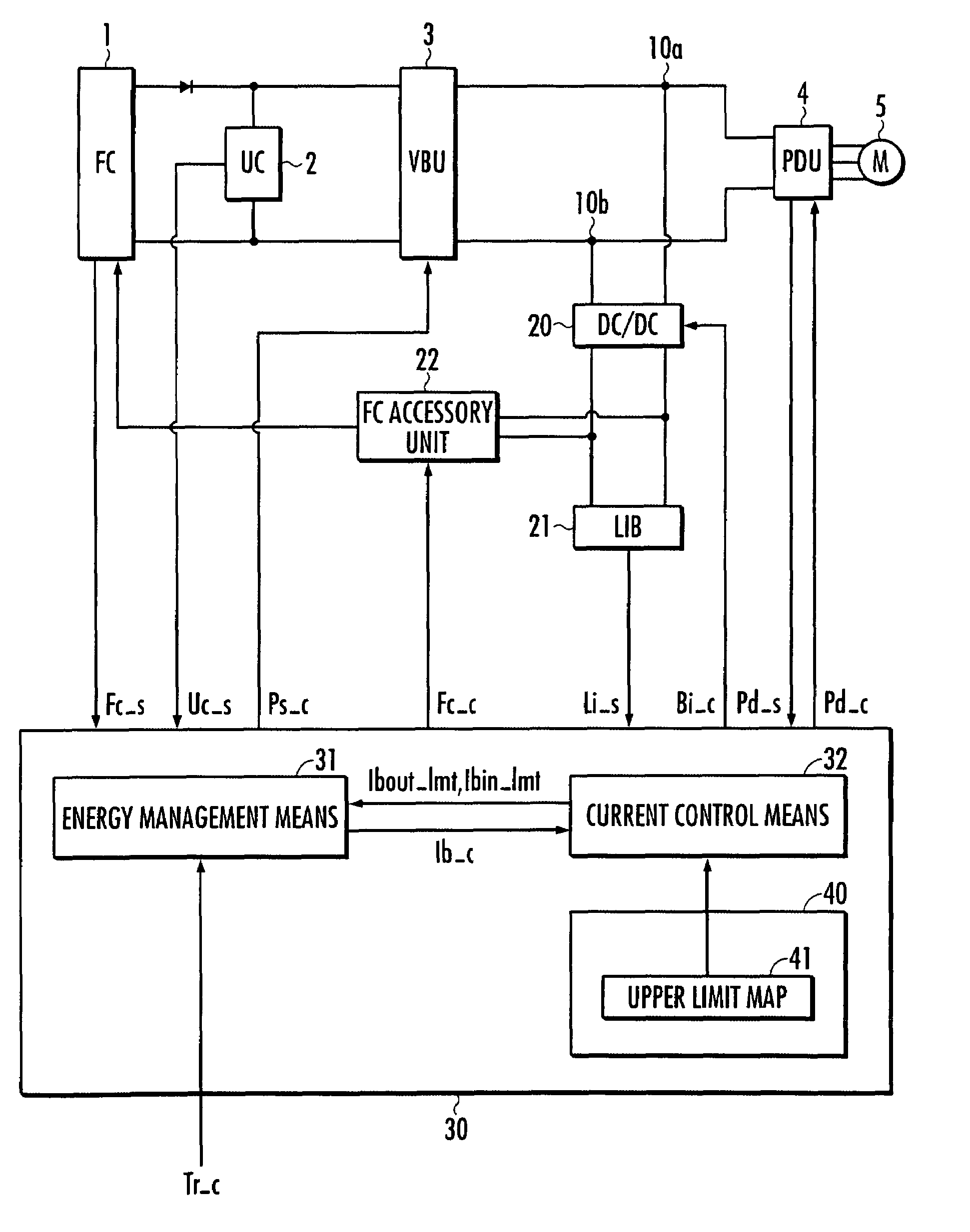
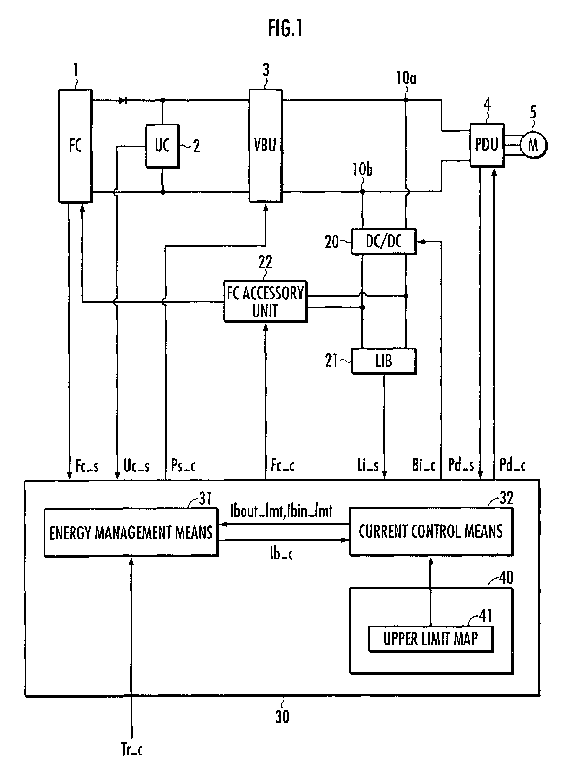
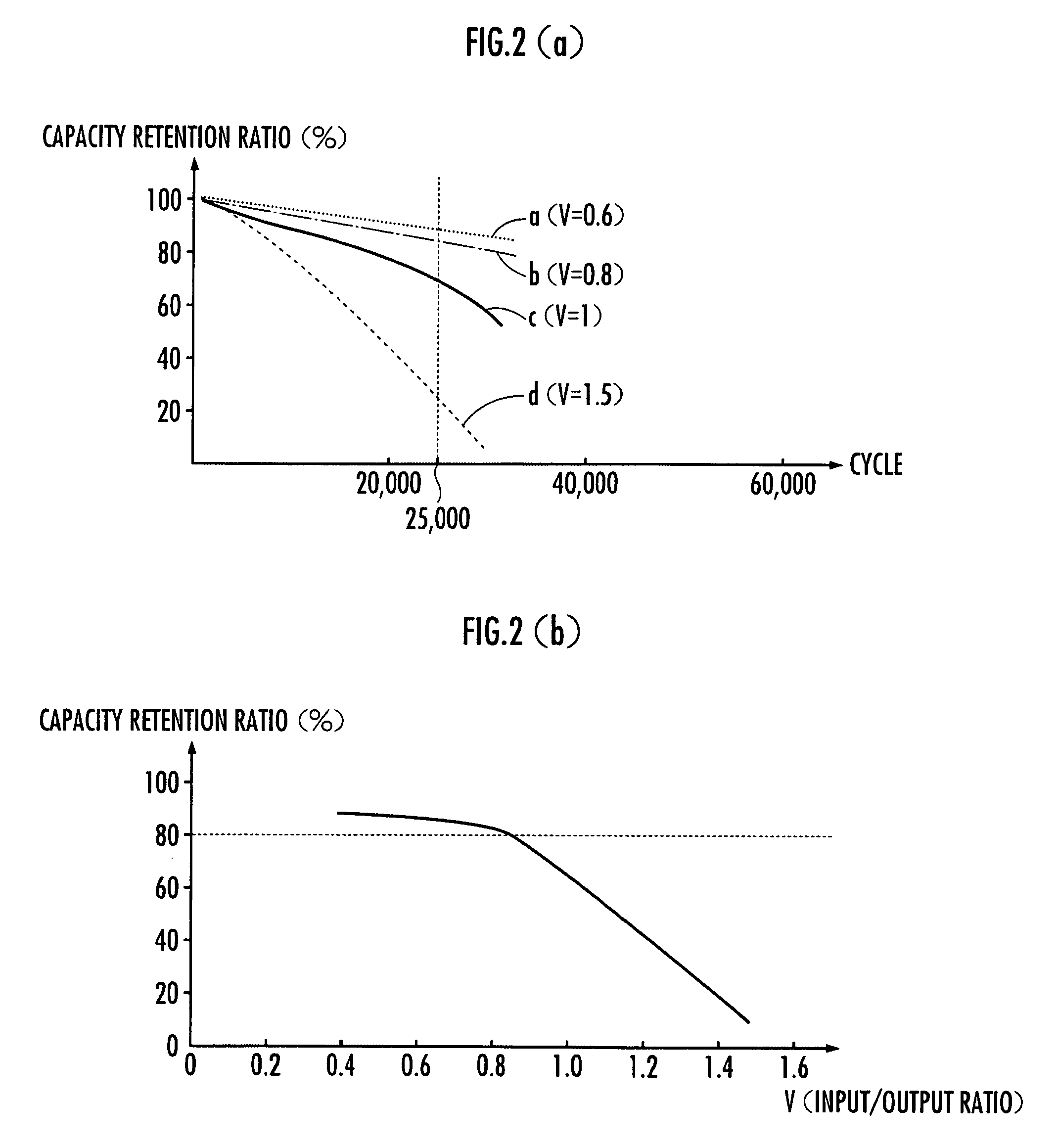
[0023]Hereinafter, a power supply device for vehicles according to an embodiment of the present invention will be described with reference to FIGS. 1 to 5. FIG. 1 is a diagram showing the entire configuration of a power supply device for vehicles according to an embodiment of the invention. FIGS. 2(a) and 2(b) are diagrams for explaining the relationship between a ratio V of input upper-limit current to output upper-limit current and the progress of deterioration of a lithium ion battery. FIG. 3 is a diagram for explaining a difference in charging amount of the lithium ion battery depending on the setting of the input upper-limit current. FIG. 4 is a diagram for explaining an upper-limit map which allocates the output upper-limit current and the input upper-limit current with respect to the SOC (State Of Charge) and temperature of the lithium ion battery. FIG. 5 is a diagram for explaining an effect obtained by making the input upper-limit current smaller than the output upper-limit...


PUM


Abstract

A power supply device for vehicles, output units (10a, 10b) thereof are connected to a motor (5), includes a fuel cell (1) which is connected to the output units (10a, 10b), a capacitor (2) which is connected in parallel to the fuel cell (1), a lithium ion battery (21) which is connected in parallel to the capacitor (2) through a DC / DC converter (20), and a current control means (32) which limits an output current of the lithium ion battery (21) to at most an output upper-limit current (Ibout_lmt) when power is supplied to the motor (5) from the lithium ion battery (21) during a power running operation of the motor (5), and limits an input current into the lithium ion battery (21) to at most an input upper-limit current smaller than the output upper-limit current (Ibin_lmt) through the DC / DC converter (20) when regenerative power of the motor (5) is recovered into the lithium ion battery (21) during a regenerative operation of the motor (5).

Description

BACKGROUND OF THE INVENTION[0001]1. Field of the Invention[0002]The present invention relates to a power supply device for vehicles, which is mounted on a vehicle, has an output unit connected to a motor which is rotated with a drive wheel, supplies drive power to the motor during a power running operation of the motor, and recovers regenerative power of the motor during a regenerative operation of the motor.[0003]2. Description of the Related Art[0004]Conventionally, a power supply device for vehicles, in which a fuel cell and a capacitor are connected in parallel to a drive motor and a secondary battery is connected in parallel to the fuel cell and the capacitor through a DC / DC converter, is known as a drive source of a fuel cell vehicle (for example, refer to Japanese Unexamined Patent Application Publication No. 2006-59689 (pages 4 to 5 and FIG. 1)).[0005]In the conventional power supply device for vehicles, during a power running operation of the motor, an output voltage of the...

Claims


Application Information

Patent Timeline
Patent Type & Authority Patents(United States)
IPC IPC(8): H02P3/14
CPCB60L11/1887B60L2210/10Y02T10/7011Y02T10/7216Y02T90/34B60L3/04B60L7/14B60L15/2009B60L50/51B60L58/13B60L58/15B60L58/16B60L58/25B60L58/40B60L2240/423B60L2240/429B60L2240/545B60L2240/547Y02T10/64Y02T10/70Y02T10/72B60L3/0046Y02T90/40
Inventor FUJINO, TAKESHIHIRAKAWA, MITSUAKINOGUCHI, MINORUKOMAZAWA, EISUKE
Owner HONDA MOTOR CO LTD
Learn More