
Fuse sensing scheme

a sensing scheme and fuse technology, applied in the field of semiconductor devices, can solve problems such as problems such as troublesome sensing or confirmation of fuse state, and achieve the effect of minimizing local variations between characteristics and quick and accurate results

Inactive Publication Date: 2011-07-26
INFINEON TECH AG
View PDF3 Cites 12 Cited by
  • Summary
  • Abstract
  • Description
  • Claims
  • Application Information

AI Technical Summary

Benefits of technology

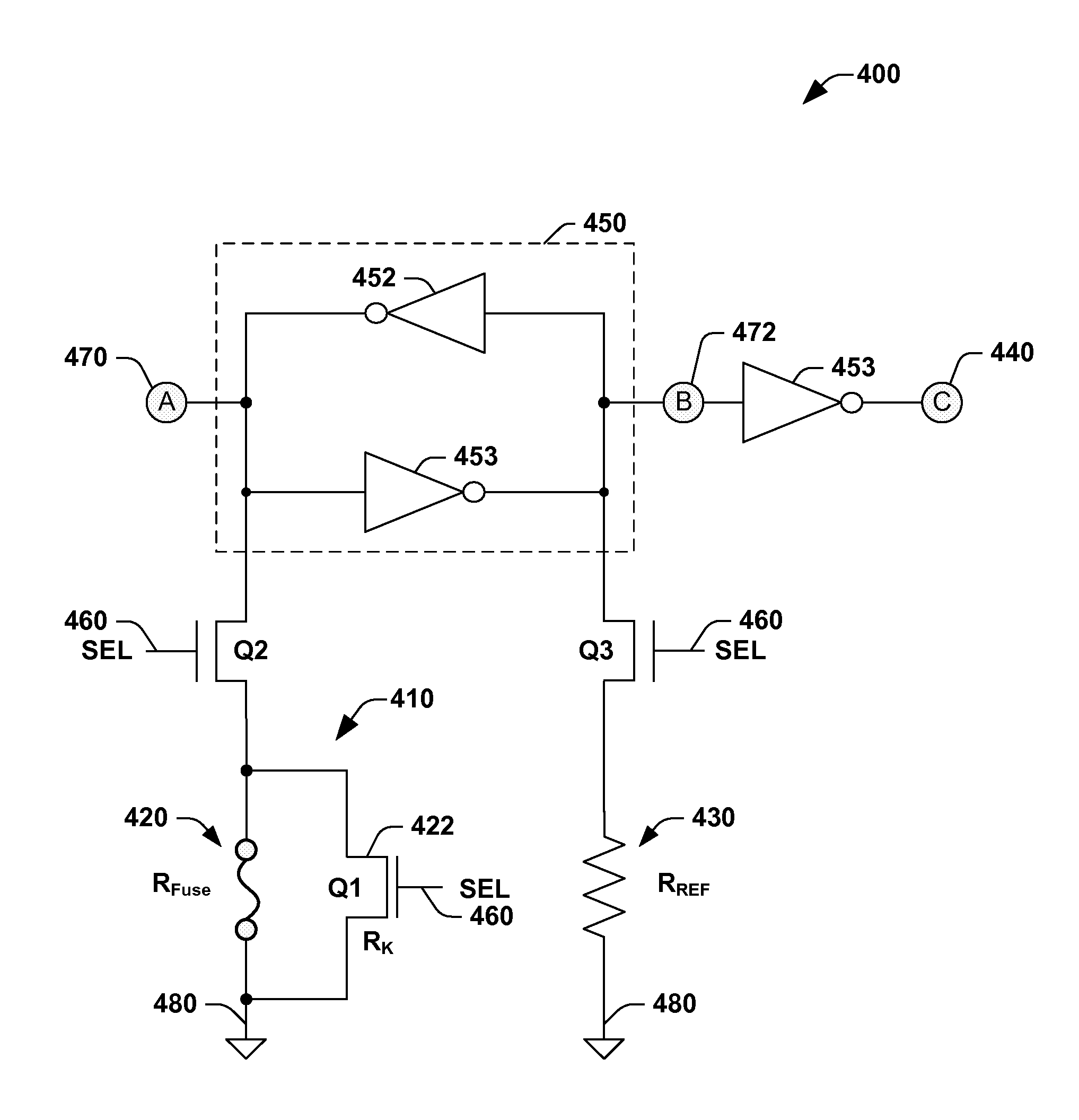
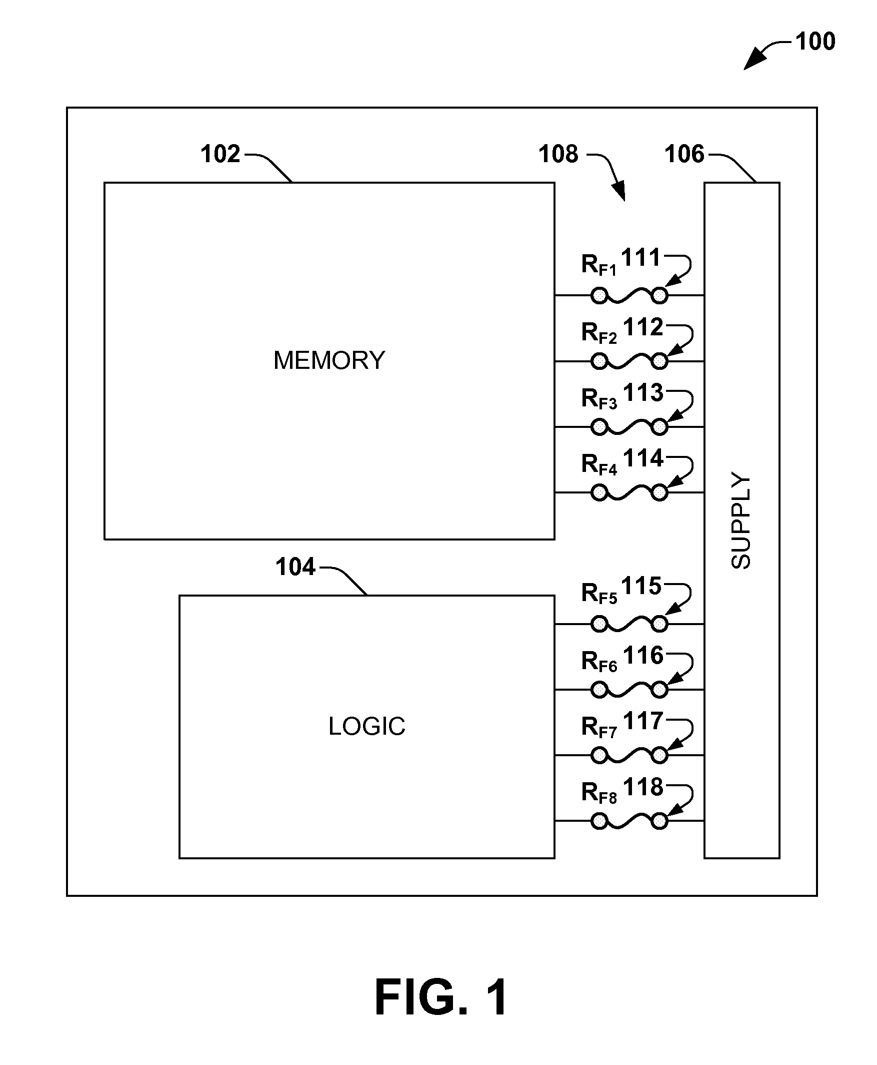
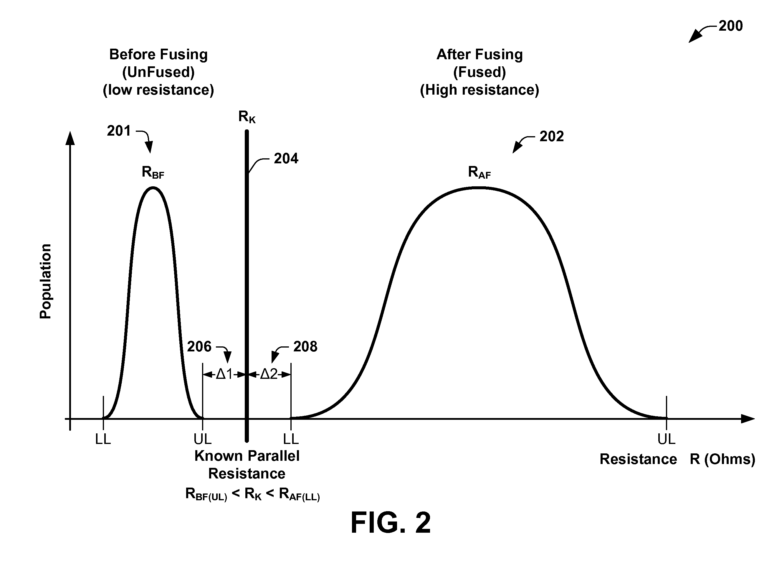
The invention is a device and method for quickly sensing the state of a programmable fuse or other programmable elements. It uses a known resistance placed parallel to the fuse element to provide a more controlled or well defined range of possible resistance values, which can be compared to a reference resistance to determine the fuse state. The fuse and known resistance are placed local to each other to minimize local variations between their characteristics. The invention provides a sense circuit associated with each fuse to read the state of the fuse. The technical effect of the invention is to enable faster and more accurate sensing of programmable fuses or elements.

Problems solved by technology

Sensing or confirming the state of a fuse may be problematic as the resistance is unknown after “fusing” the device.

Method used


Image

  • Fuse sensing scheme
  • Fuse sensing scheme
  • Fuse sensing scheme

Examples


Embodiment Construction

[0011]One or more implementations of the present invention will now be described with reference to the attached drawings, wherein like reference numerals are used to refer to like elements throughout. The invention relates to a programmable fuse circuit comprising a parallel circuit of a fuse and a resistive element having a known value, for quickly and more accurately sensing the state of the fuse, such as may be used in an integrated circuit or a semiconductor device, for example.

[0012]Conventionally, the FUSED or UNFUSED states of a fuse (e.g., programmable fuse, fuse logic, or programmable element) may be sensed, for example, by means of a sense amplifier or complex logic circuitry. However, sensing or confirming the state of a fuse may be problematic as the resistance is unknown after “fusing” or “blowing” the fuse device. In addition, it may be difficult to generate a good reference for reading the state of a programmable fuse, particularly when the distribution of possible re...


PUM


Abstract

A fuse circuit includes a fuse configured for programming a configuration of an integrated circuit device and a resistive element having a known resistance value operably coupled in parallel with the fuse. The fuse and the resistive element form a parallel circuit configured for quickly sensing a state of the fuse in relation to the known value of the resistive element. In one embodiment, the device may further include a sense circuit operably coupled to the parallel circuit combination of the fuse and the resistive element. The sense circuit is configured to sense one of a FUSED state and an UNFUSED state of the fuse, for example, based on a comparison between a reference resistance and a FUSED resistance of the fuse when coupled to the known resistance. The fuse may comprise a programmable fuse, and the resistive element may comprise a MOS transistor.

Description

FIELD OF INVENTION[0001]The present invention relates generally to semiconductors and more particularly to improved methods and devices for sensing the state of a programmable fuse.BACKGROUND OF THE INVENTION[0002]Several trends presently exist in the semiconductor and electronics industry. One of these trends is that recent generations of portable electronic devices are using more memory than previous generations. This increase in memory allows these new devices to store more data, such as music or images, and also provides the devices with more computational power and speed.[0003]To reconfigure logic, such as that which is used to store redundancy information for memory macros, electrically programmable or optically programmable fuses are often used. These fuses are generally melted (fused) by means of a high power external pulse provided either by a voltage or current pulse, or a laser pulse. Such fuses or fuse logic may be used to provide address information or other kinds of lo...

Claims


Application Information

Patent Timeline
Patent Type & Authority Patents(United States)
IPC IPC(8): H01H85/30
CPCG11C17/18H01L23/5256H01L2924/0002H01L2924/00
Inventor NIRSCHL, THOMAS
Owner INFINEON TECH AG
Learn More