
Nailing machine

a nail gun and nail head technology, applied in the field of nail guns, can solve the problems of shortened nail gun life, inability to activate the gun, and inability to maintain the finish, so as to achieve the effect of preventing the firing operation of no load

Active Publication Date: 2011-07-19
KOKI HLDG CO LTD
View PDF16 Cites 36 Cited by
  • Summary
  • Abstract
  • Description
  • Claims
  • Application Information

AI Technical Summary

Benefits of technology

The solution effectively prevents no-load firing operations by increasing the engagement depth between the activation lever and engagement member, ensuring consistent operation even with nails of varying widths, thereby maintaining the quality of the finish on materials.

Problems solved by technology

When driving operation is performed while nails are empty, the life of the nail gun is shortened, and an impact mark resultant from firing of a nail may also be left on the material, which will impair a finish.
The nail gun is configured such that, when movement of the start lever to the top dead center is hindered, the gun cannot be activated.
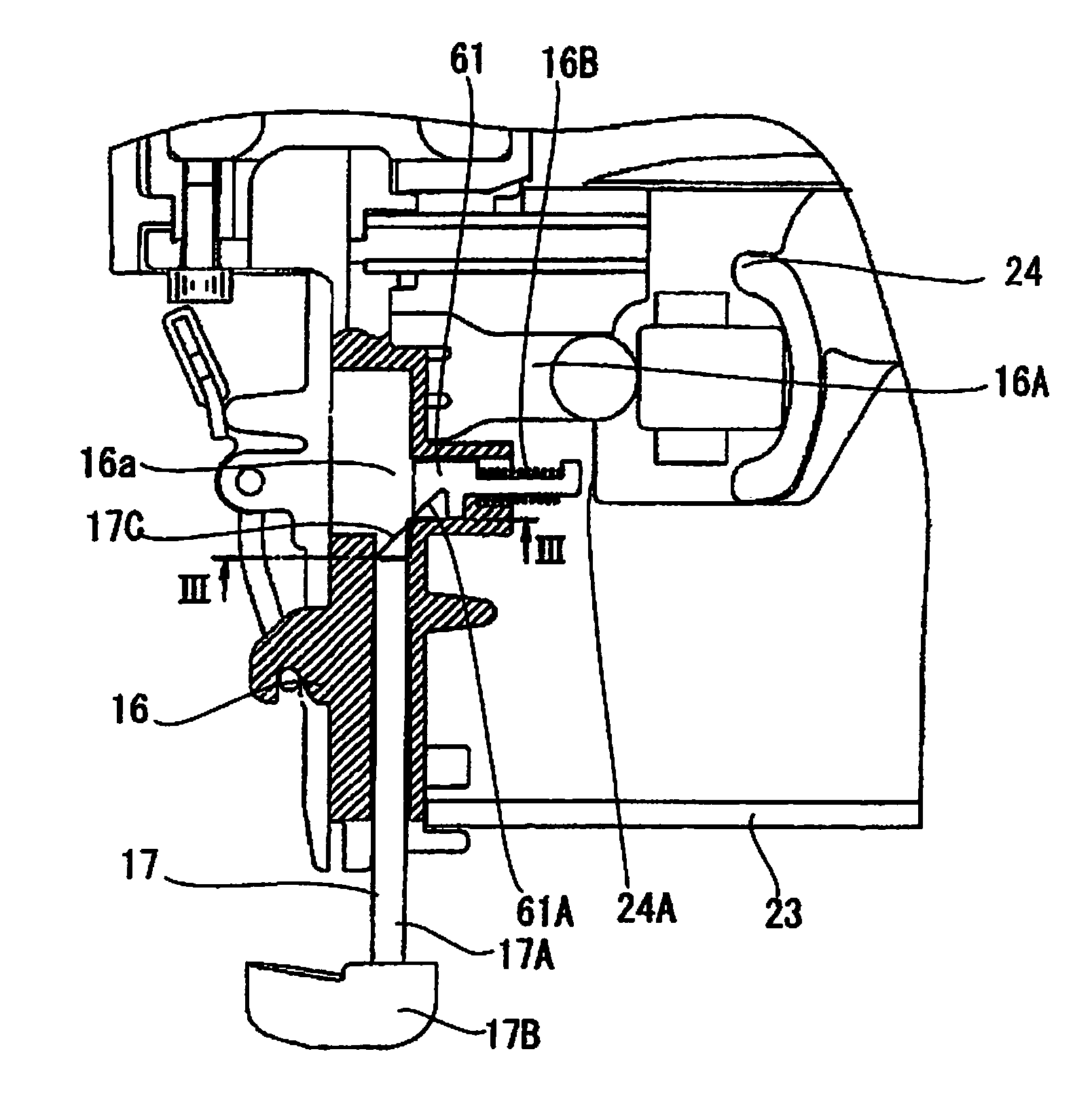
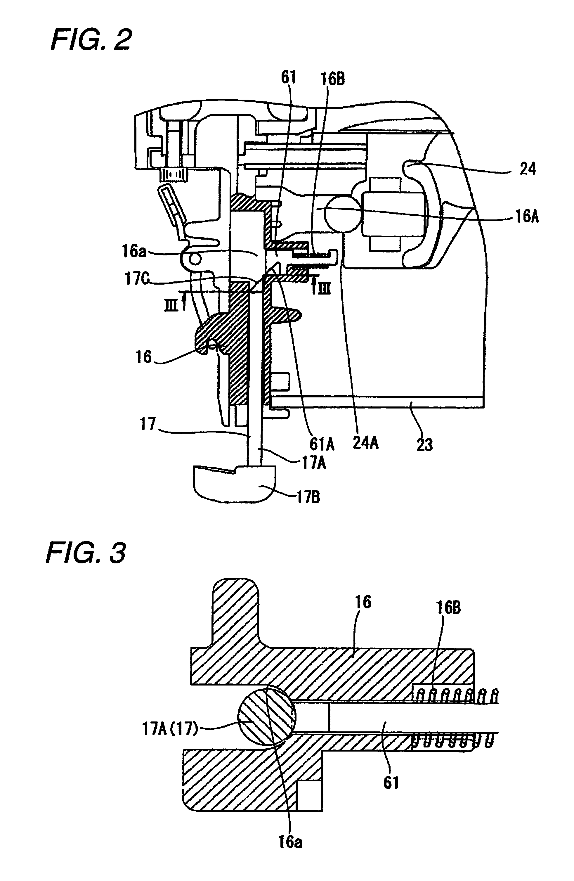
Therefore, in the case of a nail having a small width, such as a finishing nail, a sufficient amount of engagement cannot be ensured, and there has arisen a case where a no-load firing prevention mechanism fails to operate at a predetermined number of nails.
However, nails are mass-produced and involve many errors in width, and hence the errors are also amplified.
When control is performed on a per-nail basis, faulty operation arises, which sometimes results in occurrence of no-load firing.

Method used


Image

  • Nailing machine
  • Nailing machine
  • Nailing machine

Examples


first embodiment

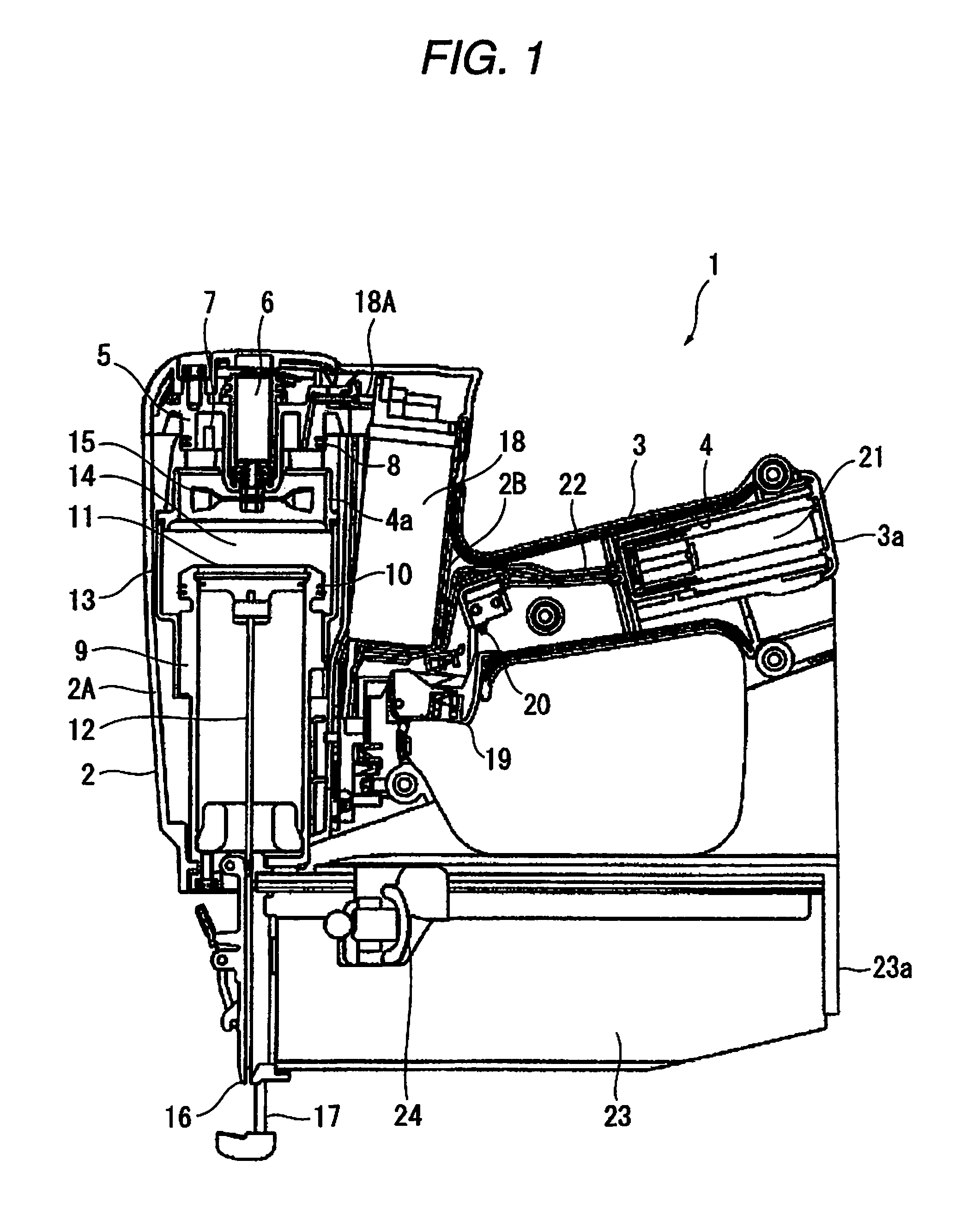
[0023]A nailing machine of the present invention will now be described hereunder by reference to FIGS. 1 through 5. A nail gun 1 is a combustion nail gun that performs nailing by means of taking gas as fuel; and has a housing 2 as an outer envelope. The housing 2 has a housing main body 2A; a gas cylinder housing 2B located on the side of the housing main body 2A; and a handle 3 extending from the gas cylinder housing 2B. A chamber head 5 is disposed at a position located too close to one end within the housing main body 2A. The chamber head 5 supports a motor 6 and an ignition plug 7 serving as ignition means. A head seal 8 is fitted on an outer peripheral surface of the chamber head 5. Moreover, a combustion gas channel is opened in the chamber head 5.

[0024]A cylinder 9 is fastened to a position in the housing main body 2A opposite to the motor 6, and a cylinder seal 10 is fitted to an outer peripheral surface of one side of the cylinder 9. A piston 11 serving as a power unit is p...

second embodiment

[0038]A nailing machine of the present invention will now be described by reference to FIGS. 6 through 8. A nail gun shown in FIG. 6 is a pneumatic nail gun that performs nailing by means of taking compressed air as power. A housing 102 and a handle 103 located at one side of the housing 102 are provided integrally in the nail gun. Compressed air from an unillustrated compressor is accumulated, by way of an unillustrated air hose, in a pressure accumulation chamber 103a formed in the handle 103 and the housing 102 of the nail gun 101. A cylindrical cylinder 109 is provided in the housing 102, and a piston 111 is provided in the cylinder 109 so as to become vertically slidable. A driver blade 112 is formed integrally on the piston 111, and a nail is driven by the driver blade 112.

[0039]A pneumatic chamber 102a for accumulating compressed air for returning the driver blade 112 to the top dead center is provided at a lower-end outer periphery of the cylinder 109. A non-return valve 102...


PUM

PropertyMeasurementUnit
movementaaaaaaaaaa
widthaaaaaaaaaa
depth of engagementaaaaaaaaaa

Abstract

According to an aspect of the present invention, there is provided a nailing machine including: a housing; an ejection section in the housing; an activation lever provided in the ejection section to be movable inside a traveling course; a magazine holding nails; a feeder urging the nails to feed the nails; and an engagement member engaged with the feeder so that, when an amount of remaining nails becomes to a predetermined number, the engagement member is moved toward a first direction to protrude into the traveling course; wherein one of the activation lever and the engagement member includes a slope portion so that the engagement member is further moved toward the first direction through the sliding contact therebetween.

Description

TECHNICAL FIELD[0001]The present invention relates to a nailing machine.BACKGROUND ART[0002]A nailing machine, such as a nail gun, starts operation by means of synergistic combination of operation for activating a trigger placed in the vicinity of a handle and operation for pressing a lower end of a start lever located in the vicinity of an ejection section at an exit, from which a fastener such as a nail is fired, against a material subject to driving action (hereinafter called simply a “material”), such as wood. A nail in the ejection section is fired from the ejection section. The lower end of the start lever is located in the vicinity of the ejection section and pressed toward a bottom dead center by means of a spring that is supported so as to be movable between the bottom dead center at a leading end of the ejection section and the top dead center at a base end of the ejection section. Before operation of the nailing machine, the start lever is situated at the bottom dead cent...

Claims


Application Information

Patent Timeline
Patent Type & Authority Patents(United States)
IPC IPC(8): B25C1/04
CPCB25C5/1689
Inventor AKIBA, YOSHITAKAIIJIMA, YOSHIMITSU
Owner KOKI HLDG CO LTD
Learn More