
Wire tray and tent frame incorporating same

a technology of wire tray and tent frame, which is applied in the field of tents, can solve the problems of time-consuming and even frustrating, nothing can be wrapped around the rafter, and the tent and the hanging of these accessories are still aesthetically disconcerting, so as to enhance the aesthetic appeal of the wire tray

Active Publication Date: 2011-07-05
JOHNSON OUTDOORS
View PDF13 Cites 8 Cited by
  • Summary
  • Abstract
  • Description
  • Claims
  • Application Information

AI Technical Summary

Benefits of technology

"The present invention provides a wire tray for a tent that can securely store and support wires or other devices that need to be hung from the tent. The wire tray includes a wire storing channel for securely storing wires and prevents them from draping between adjacent structural members of the tent. The wire tray can be mounted to the tent frame using bolts, snap connections, or other mounting devices. The wire tray includes mounting clips that engage with attachment structures on the tent frame to securely hold the wire tray. The wire tray also includes a wire support flange that provides support for the wires. The wire tray can be easily attached to the tent frame and provides a more organized and aesthetically pleasing appearance."

Problems solved by technology

However, assembly of the tent and hanging of these accessories has been time consuming and even frustrating.
However, this still aesthetically displeasing because another cord, bungee strap or other device is then required to secure the middle section of the wire to the rafter.
Further, in many tents, the rafters are directly secured to the fabric panels forming the shell such that nothing can be wrapped around the rafter to support the free hanging portion of the wire.
Finally, weaving wires between the purlins and the fabric panels can be extremely time consuming and can occur at extremely elevated locations.

Method used


Image

  • Wire tray and tent frame incorporating same
  • Wire tray and tent frame incorporating same
  • Wire tray and tent frame incorporating same

Examples


Embodiment Construction

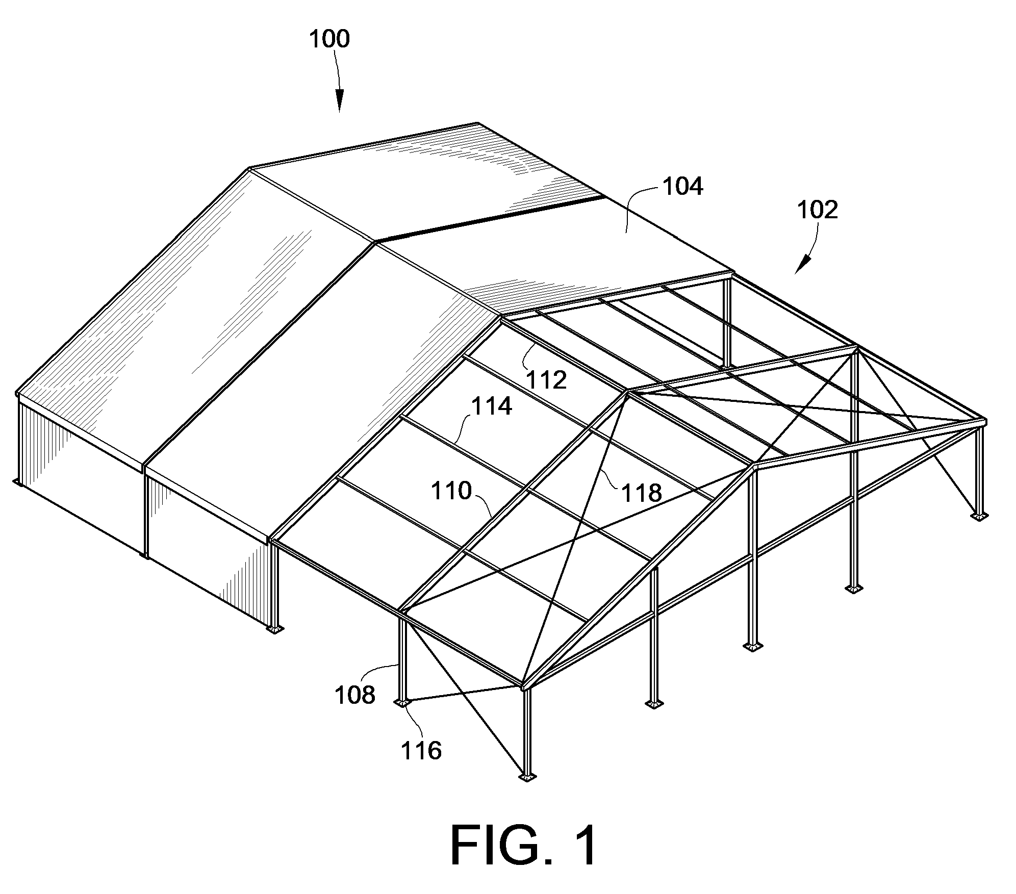
[0042]FIG. 1 illustrates a partial illustration of a tent 100 including structural members in accordance with the teachings of the present invention. The tent 100 includes a tent frame 102 that supports a shell 104 to provide a shelter or building like structure.

[0043]The tent frame 102 is generally constructed of a plurality of structural members including a plurality of legs 108 that generally define the vertical walls of the tent, a plurality of rafters 110 that extend at an angle relative to the legs 108 and that meet at the peak 112 of the tent 100 and a plurality of purlins 114 that extend horizontally between the rafters 110 and generally parallel to the peak 112. Typically, purlins 114 are made of smaller profiles. The peak 112 is formed by purlins 114. Purlins in this position are also referred to as ridge purlins. The illustrated tent frame 102, is a clear span tent frame that is free of interior poles.

[0044]The legs 108 are mounted to feet 116 which rest on the ground upo...


PUM


Abstract

A wire tray and tent frame structural members are provided. The structural members include a utility channel or C-shaped channels to which wire trays can be mounted. More particularly, mounting structures of the wire tray insert into or otherwise engage the utility channel or engage the C-shaped channels and secure the wire tray to the structural members. The utility channel or C-shaped channels can include at least one undercut to prevent removal or disengagement of the mounting structure of the wire tray from the structural member. Similarly, methods of using the wire tray including resiliently biasing mounting structure of the wire tray to attach it to the structural member are provided.

Description

CROSS-REFERENCE TO RELATED PATENT APPLICATIONS[0001]This patent application claims the benefit of U.S. Provisional Patent Application No. 61 / 037,200, filed Mar. 17, 2008, the entire teachings and disclosure of which are incorporated herein by reference thereto.FIELD OF THE INVENTION[0002]This invention generally relates to tents and more particularly to tents, tent frames and devices for organizing wires for use with accessories hung from tent frames.BACKGROUND OF THE INVENTION[0003]A tent can be used for providing a shelter and environment for large gatherings and celebrations such as theatrical events, wedding receptions and conventions. A shell of the tent provides shelter and defines the environment for the event. The shell is typically formed from one or more fabric panels that are supported by a frame. The frame of a large tent typically includes a plurality of interconnected structural members that combine to support the shell. The structural members may include vertical legs...

Claims


Application Information

Patent Timeline
Patent Type & Authority Patents(United States)
IPC IPC(8): E04H15/32E04B9/04
CPCE04H15/18
Inventor REYEN, JAMES G.HAMILTON-JONES, MATTHEW H.WIEGAND, JOSEPH G.
Owner JOHNSON OUTDOORS
Learn More