Audio output apparatus
a technology of audio output and output device, which is applied in the direction of electrical transducers, volume compression/expansion, gain control, etc., can solve the problems of target sounds not being heard, lost in other sounds, etc., and achieve the effect of improving the separation of audibility of a plurality of sounds
- Summary
- Abstract
- Description
- Claims
- Application Information
AI Technical Summary
Benefits of technology
Problems solved by technology
Method used
Image
Examples
first embodiment
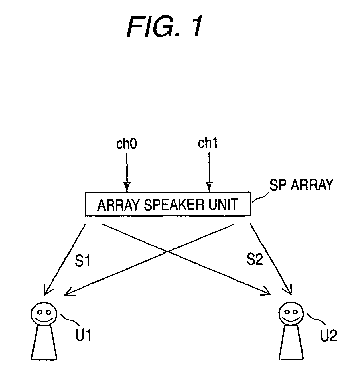
[0069]Hereinafter, embodiments of the invention will be described in detail with reference to the drawings. FIG. 1 is a diagram illustrative of the principle of a first embodiment.
[0070]As similar to the audio output apparatus before, in an audio output apparatus according to the embodiment, directivity is controlled to emit sounds S1 and S2 from an array speaker unit SParray so that the first sound S1 and the second sound S2 separately have different directivities. However, at this time, the sound levels are adjusted so as to equal the levels of a first sound signal ch0 and a second sound signal ch1 which are the base of the sounds S1 and S2, and the sound signals ch0 and ch1 are inputted to the array speaker unit SParray.
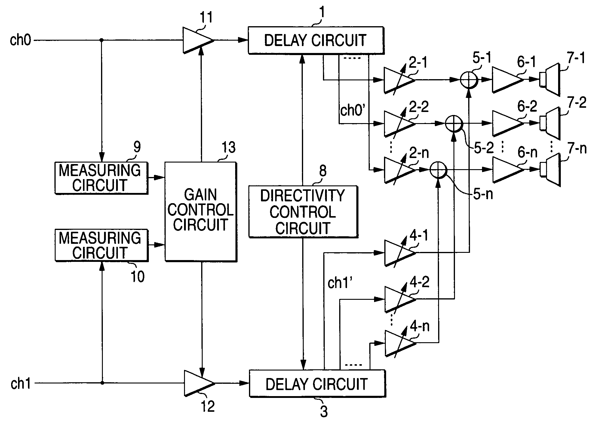
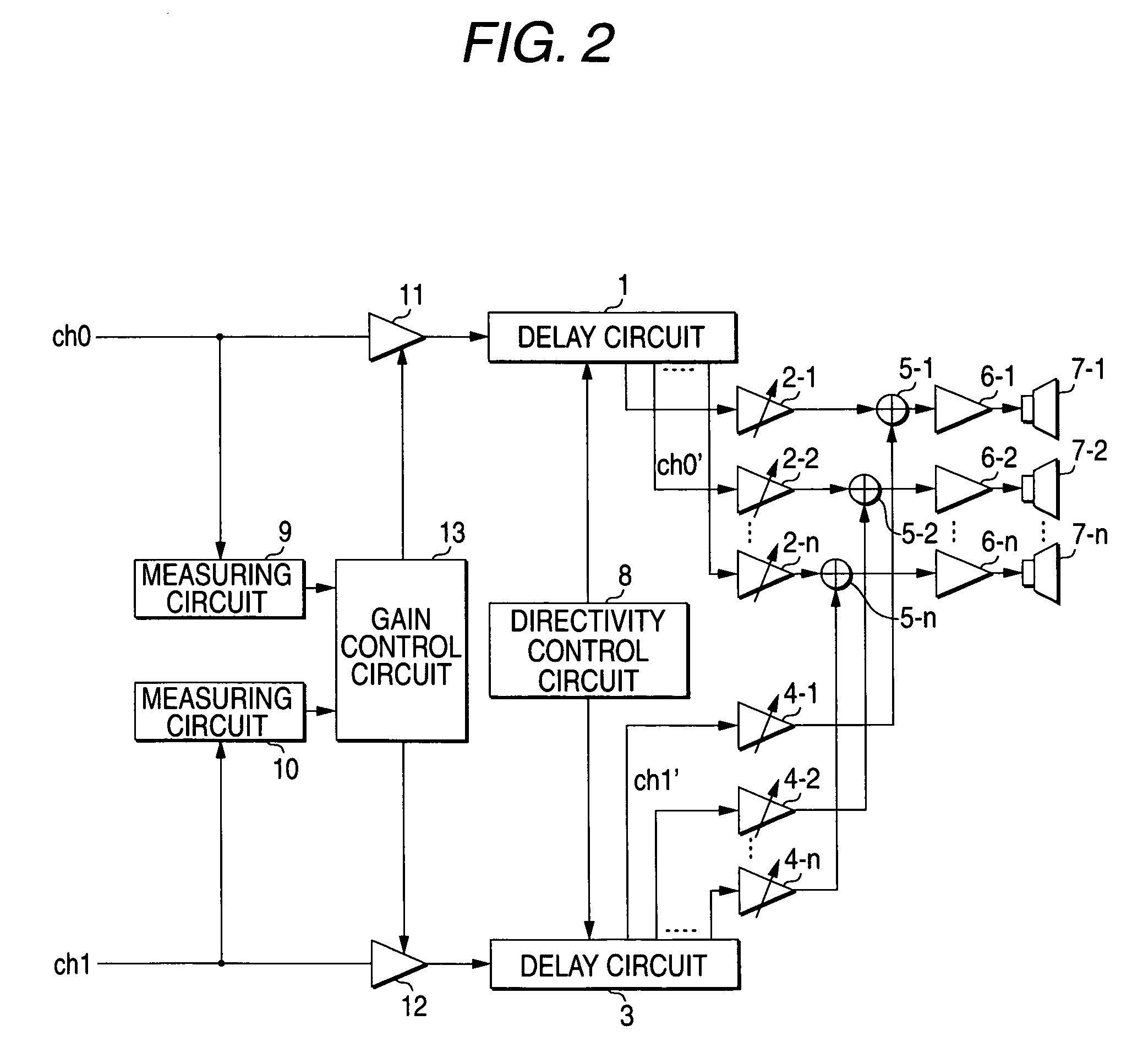
[0071]FIG. 2 is a block diagram showing the configuration of the audio output apparatus according to the first embodiment of the invention. The audio output apparatus shown in FIG. 2 has a measuring circuit 9 which measures the level of the first sound signal ch0,...
second embodiment
[0086]Next, a second embodiment of the invention will be described. FIG. 6 shows a block diagram showing the configuration of an audio output apparatus according to the second embodiment of the invention, and the same numerals and signs are designated to the same configuration as that shown in FIG. 2. The audio output apparatus according to the embodiment shows a more specific example of the first embodiment.
[0087]A measuring circuit 9 according to the embodiment is formed of a rectifier circuit 101 and peak hold circuits 102 and 103. The rectifier circuit 101 rectifies the inputted first sound signal ch0 to the absolute value. The peak hold circuits 102 and 103 hold and output the greatest value among input values up to now in such a way that the hold value is maintained when the value inputted from the rectifier circuit 101 is equal to or smaller than the current hold value whereas an input value is made to a new hold value when the input value exceeds the hold value. When such a ...
third embodiment
[0096]In the first and second embodiments, the gain coefficients of the sound level adjusting circuits 11 and 12 are set so as to equal the levels of the first sound signal ch0 and the second sound signal ch1 outputted to the array speaker unit (the delay circuits 1 and 3). However, the gain coefficients may be set so that the difference between the first sound signal ch0 and the level of the second sound signal ch1 is made constant.
[0097]FIG. 7 is a block diagram showing the configuration of an audio output apparatus according to a third embodiment of the invention, and the same numerals and signs are designated to the same configuration as that shown in FIG. 6. In the audio output apparatus according to the embodiment, a gain control circuit 13a is used instead of the gain control circuit 13 shown in FIG. 6. The gain control circuit 13a is added with a function that adds a given amount of offset set by a viewer to the outputs of the subtracters 107, 110, 113 and 116 in the gain co...
PUM
 Abstract
Description
Claims
Application Information
 - R&D
- Intellectual Property
- Life Sciences
- Materials
- Tech Scout
- Unparalleled Data Quality
- Higher Quality Content
- 60% Fewer Hallucinations
Browse by: Latest US Patents, China's latest patents, Technical Efficacy Thesaurus, Application Domain, Technology Topic, Popular Technical Reports.
© 2025 PatSnap. All rights reserved.Legal|Privacy policy|Modern Slavery Act Transparency Statement|Sitemap|About US| Contact US: help@patsnap.com


