Light string with improved shunt system

a shunt system and light string technology, applied in the direction of light fastenings, coupling device connections, lighting and heating apparatus, etc., can solve the problem of the entire string of bulbs going out, and achieve the effect of reliable conductive connection, safe decorative light use, and convenient assembly

Inactive Publication Date: 2011-06-28
DIANQING ZHENG +1
View PDF22 Cites 3 Cited by
  • Summary
  • Abstract
  • Description
  • Claims
  • Application Information

AI Technical Summary

Benefits of technology

[0006]One object of this utility model is to overcome the aforesaid drawbacks of the prior art by providing a decorative light capable of preventing failure of the complete string of bulbs when an individual bulb is removed or bums out.
[0007]Another object of this utility model is to provide a decorative light that is easy to assemble.
[0008]A third object of this utility model is to provide a decorative light that ensures reliable conductive connection by having a conductive device in a socket make full contact with the terminals when a bulb comes off
[0014]As compared to the prior art, when an individual bulb is removed from the bulb base in the decorative light of this utility model, the elastic conductive coil can complete the circuit connection reasonably immediately due to the expansion of the ring so as not to affect operation of the whole string of bulbs. The elastic conductive coil may be pre-mounted into the retainer and then the retainer incorporating the elastic conductive coil as a whole is fitted into the socket. Therefore, the decorative light of this invention has a feature that it is easy to assemble. In case the bulb base and the bulb come off from the socket, the elastic conductive ring will make contact with the terminals at both sides. Moreover, the decorative light of this invention features reliable conductive connection without false contact and arcing. Because decorative lights are often moved by the wind or moved around by the user, this feature makes the decorative light safer for use.

Problems solved by technology

Due to the serial connection, a blown fuse or the removal of one or more of the bulbs will interrupt the complete series circuit connection.
However, according to the technology disclosed in the China Patent CN2253524Y, the resistance wire or fuse is disposed within the bulb, so when one bulb in a decorative light string consisting of such bulbs comes off, an open circuit will still occur, causing the entire string of bulbs to go out.

Method used


Image

  • Light string with improved shunt system
  • Light string with improved shunt system
  • Light string with improved shunt system

Examples


first embodiment

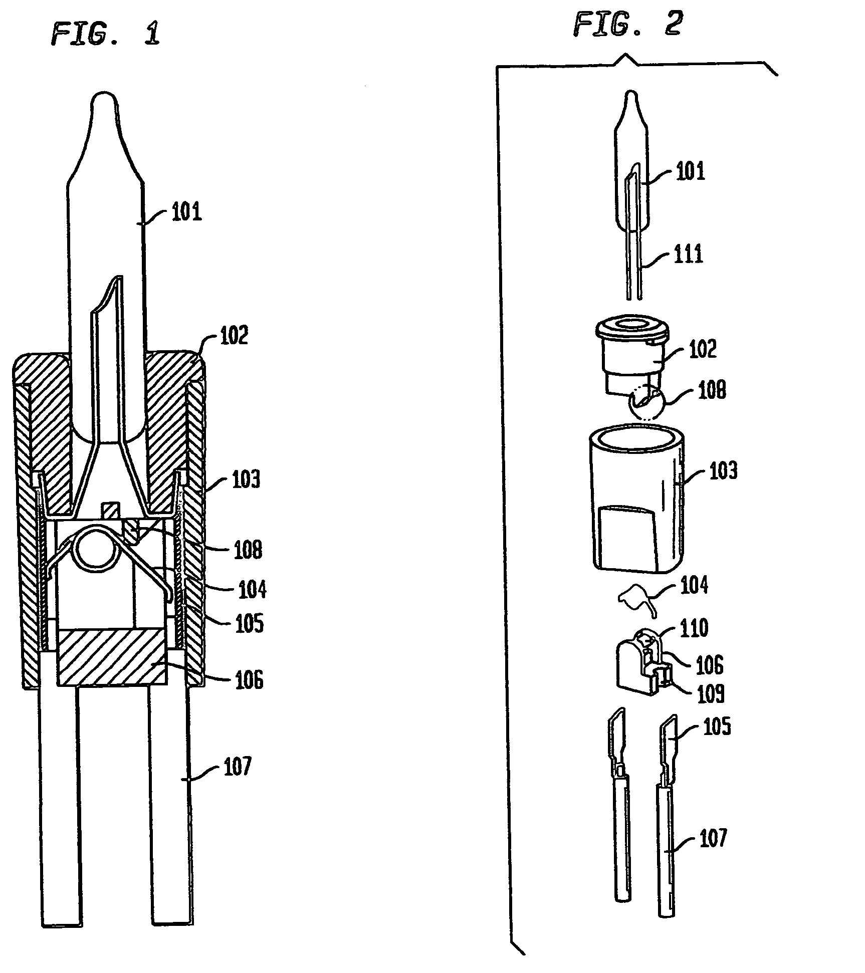
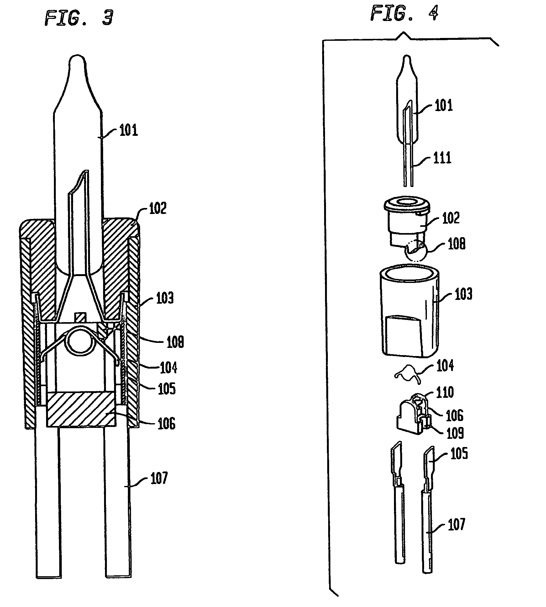
[0022]Hereinafter, this utility model will be further described with reference to the drawings. FIGS. 1-4 show the present utility model. Bulb 101 and lamp base 102 are preassembled together, and then an assembled body of the bulb 101 and the lamp base 102 is inserted into one end of the lamp holder 103. The copper terminals 105 are pressed into the ends of the wires 107; there are two wires 107 as well as two copper terminals 105 provided; the copper terminals 105 are inserted in the other end of the lamp holder 103. As shown in FIG. 1, the two copper terminals 105 are respectively connected to the two electrodes 111 of bulb 101. There is a bulge 108 at the end of the lamp base 102 facing to the copper terminals 105. The bulge is close to one of the two terminals 105. A torsion spring 104 made with steel wire is arranged in the lamp holder 103. The torsion spring 104 is provided with two feet corresponding to the positions of the copper terminals 105, one foot is in contact with on...

second embodiment

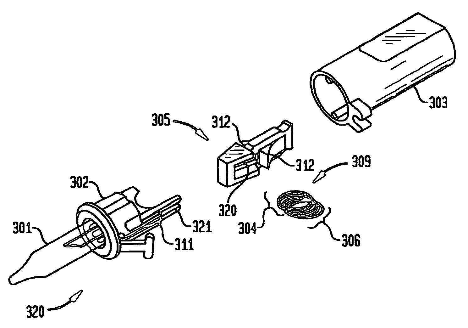
[0024]Referring to FIGS. 5 and 6, the present invention is a decorative light comprising a socket 203, a bulb base 202, a bulb 201 and two terminals 207. The bulb 201 is disposed on the bulb base 202, with two electrodes 1011 of the bulb 201 passing through the bulb base 202 to form two contacts at the bottom of the bulb base 202. The socket 203 is shaped like a barrel, the bulb base 202 is inserted into the top end of the bulb base 203, and the two terminals 207 are inserted to the bottom end of the socket, with the two electrodes at the bottom of the bulb base 202 contacting against the two terminals 207 respectively. The terminals 207 are pressed to corresponding power leads 204. The socket 203 is further provided with a retainer 205 therein, which has an opening laterally extending therethrough and an elastic, conductive ring 206 disposed within the opening. A thickness of the elastic, conductive ring 206 is smaller than a width of the opening so that the elastic conductive ring...


PUM


Abstract

This utility model relates to a decorative light, and particularly, to a decorative light capable of avoiding an open circuit condition on an entire string of bulbs that operate in series when an individual bulb is removed. The decorative light comprises a socket, a bulb base, a bulb and two terminals, wherein the socket is provided with a retainer therein, which has an opening laterally extending therethrough, and an elastic, conductive ring or coil with a thickness smaller than a width of the opening is disposed within the opening. When the elastic ring or coil is in a natural state, the elastic ring extends outside the retainer through the opening at two sides of the retainer. The bulb base is further provided with an inserting partition at the bottom thereof The elastic conductive ring has two states: one is a separating state where the bulb base is inserted into the socket. In this first state, the inserting partition of the bulb base separates one side of the elastic ring or coil from the corresponding terminals. The other state is a conducting state of the two terminals when the bulb base is removed from the socket. In this second state both sides of the elastic, conductive ring or coil provide contact with the two terminals respectively. This utility model provides a decorative light capable of preventing failure of the complete string of bulbs when any bulb is removed.

Description

CROSS-REFERENCES TO RELATED APPLICATIONS[0001]This application claims priority under 35 USC §119 from U.S. Provisional Patent Application No. 61 / 072,458, filed Mar. 31, 2008 and having the title LIGHT STRING, the disclosure and application of which is incorporated by reference herein in its entirety.[0002]This application also claims priority under 35 USC §120 as a continuation-in-part from U.S. patent application Ser. No. 11 / 977,621, filed Oct. 25, 2007 now U.S. Pat. No. 7,591,658 and having the title LIGHT STRING WITH IMPROVED SHUNT SYSTEM, which in turn claims priority under 35 USC §119 from Chinese patent application Serial. No. 200620015418.0, filed on Oct. 25, 2006, entitled DECORATIVE LIGHT, all the disclosures and applications of which are incorporated by reference herein in their entirety.[0003]This application is further related to U.S. patent application Ser. No. 12 / 383,934, filed Mar. 30, 2009 and having the title LIGHT STRING WITH IMPROVED SHUNT SYSTEM, which in turn cl...

Claims


Application Information

Patent Timeline
Patent Type & Authority Patents(United States)
IPC IPC(8): H01R29/00
CPCF21V19/0005H01R33/96H01R33/06F21S4/001F21W2121/00F21S4/10
Inventor DIANQING, ZHENGCHEN, QI
Owner DIANQING ZHENG
Why Eureka
Try Eureka