System and method for estimating inertial acceleration bias errors

a technology of inertial acceleration and bias error, applied in the field of system and method for estimating bias errors, can solve the problems of expected gls failure mode and their affect on the aircraft guidance system, most common failure mode of gls will be a total loss of external updates, gls position and velocity,

Active Publication Date: 2011-06-14
THE BOEING CO
View PDF15 Cites 9 Cited by
  • Summary
  • Abstract
  • Description
  • Claims
  • Application Information

AI Technical Summary

Problems solved by technology

However, a key issue associated with GLS CAT II / III operations are the expected GLS failure modes and their affect on the aircraft guidance system.
It is anticipated that the most common failure mode for GLS will be a total loss of external updates, such as the GLS positions and velocities, for an extended period of time, such as for hundreds of seconds.
As a result, the loss of external updates causes the location of the vehicle to be inaccurate.
However, this initial filtering technique relies on instantaneous detection of a GLS system failure.
If there is any delay in the detection of the GLS failure, the inertial bias correction term is subject to corruption by erroneous GLS position information during the period of time that the GLS failure is present but undetected.
Unfortunately this poses a problem for GLS approaches because the same position information being sent to the inertial units for synthesis of the GPS blended inertial navigation solution is also being used to synthesize the GLS deviations.
If no alternative inertial outputs (independent of GPS / GLS failures) are available, fail-operative autoland in the presence of GLS signal loss is compromised by potential corruption from the GPS supplement to the inertial rates.
However, a pure translation of accelerations is not enough to guarantee accurate bias estimation, depending on the behavior of the inertial error.
This results in a mismatch in the comparison of the inertial error (fixed to the local accelerometer frame) and the fixed-earth deviations referenced to the runway which causes the cross-runway bias detectable by the previously patented filter schemes to be subject to any differences between the aircraft attitude and the runway.
Thus, the bias estimated through the approach is potentially non applicable when the GLS signal becomes invalid.
In this case, without an alternative means of estimating the inertial errors in their local frame, a potentially costly upgrade in the IRU is required to outfit it with either high accuracy gyros or additional computational power to handle the added complexity of a separate navigation solution output synthesized without GPS aiding to enable fail-operational GLS autoland.

Method used


Image

  • System and method for estimating inertial acceleration bias errors
  • System and method for estimating inertial acceleration bias errors
  • System and method for estimating inertial acceleration bias errors

Examples


Embodiment Construction

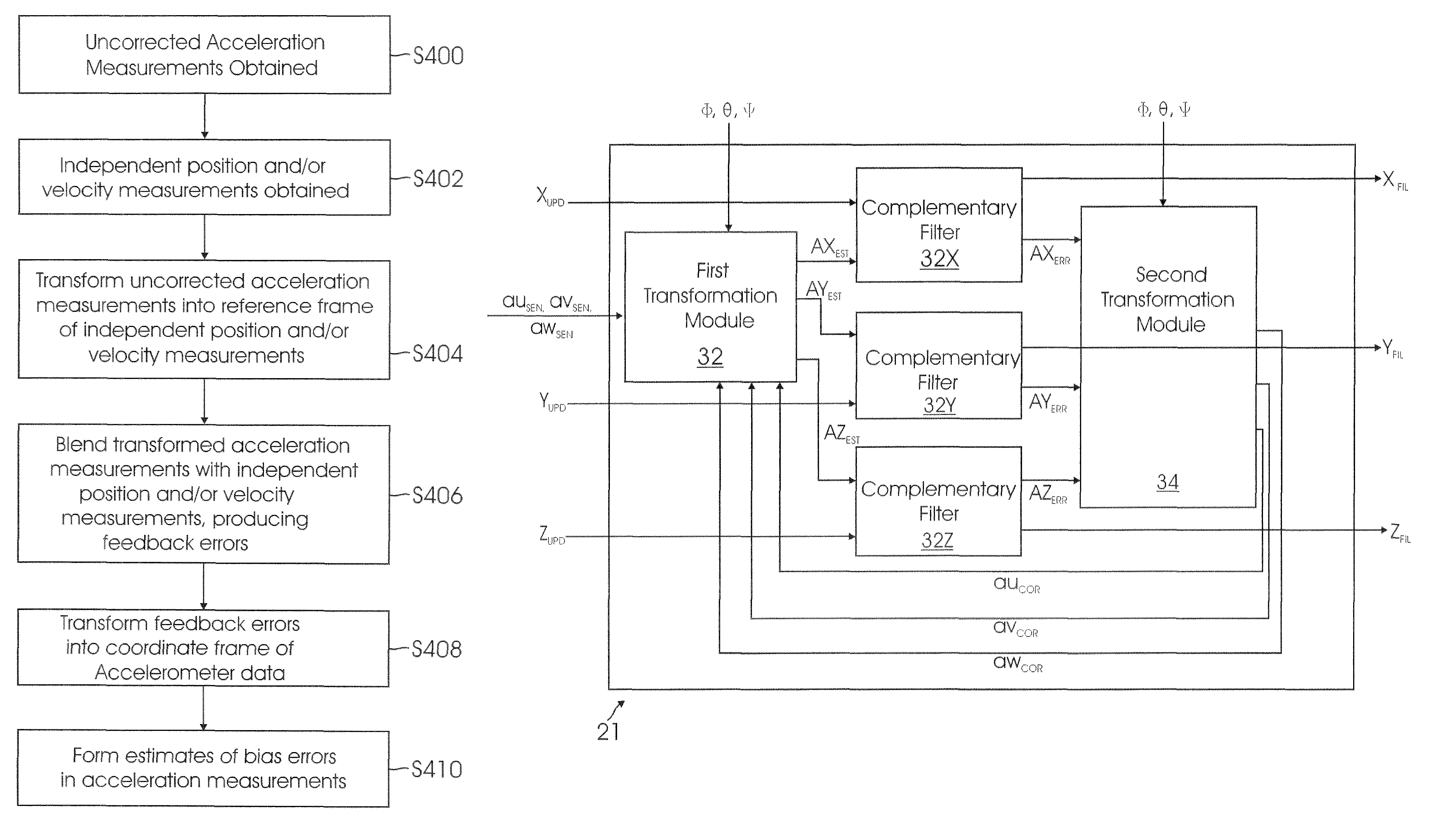
[0024]The disclosure provides an onboard navigation system and method for estimating inertial acceleration bias errors without the computational burden and / or complexity of conventional filtering schemes. Instead, a set of complementary filters is used to combine accelerometer outputs with position and / or velocity updates from an independent source.

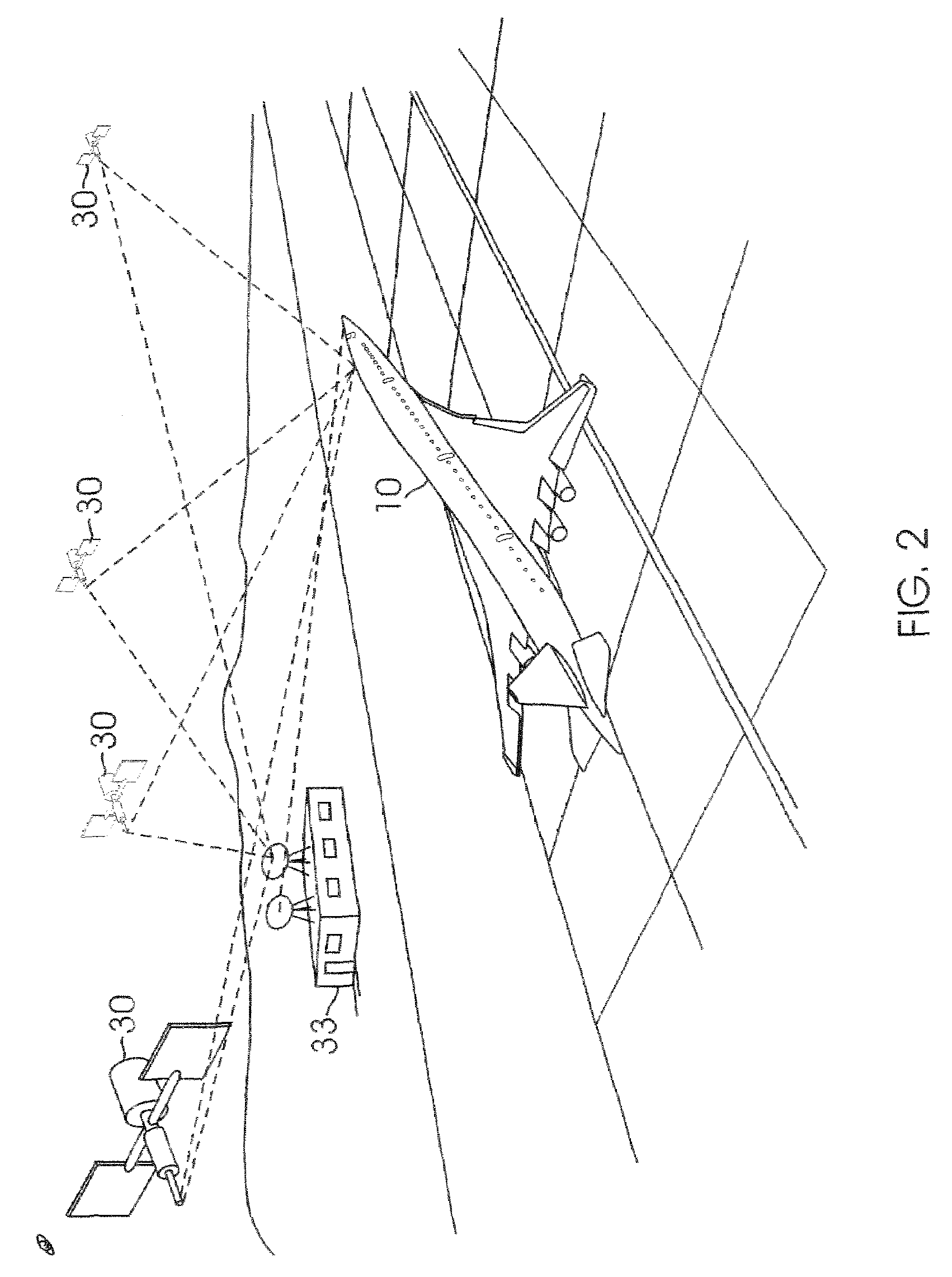
[0025]Although the system and method of the disclosure are described with reference to an autopilot system for an aircraft, those skilled in the art will recognize that the principles and teachings described herein may be applied to a variety of navigation systems.

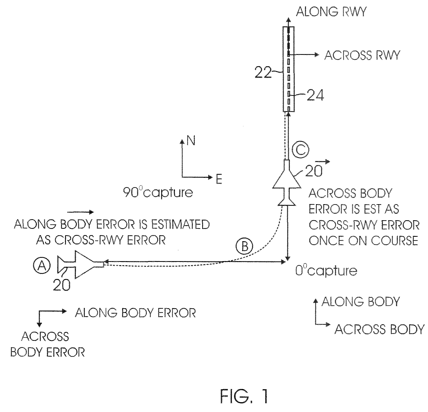
[0026]FIG. 1 is a schematic diagram of an aircraft 20 using an onboard navigation system to autoland on runway 22. At position A, aircraft 20 is flying in an easterly direction, while runway 22 at point C has a northerly heading. In order to land on runway 22, aircraft 20 must maneuver from point A to point C; through point B (a 90° change in direction) and align itself with run...


PUM


Abstract

A method for estimating inertial acceleration bias errors including obtaining uncorrected acceleration measurements on board a vehicle; obtaining independent position and independent velocity data of the vehicle; transforming the uncorrected acceleration measurements into a reference frame of the independent position and independent velocity data; blending the transformed acceleration measurements with the independent position and the independent velocity data to produce feedback errors; transforming the feedback errors into the reference frame of the acceleration measurements; multiplying the feedback errors by a gain and integrating to estimate the acceleration measurement bias errors.

Description

BACKGROUND[0001]1. Field of Disclosure[0002]The disclosure relates generally to an onboard navigation system and more particularly, to a system and method for estimating the bias errors associated with inertial acceleration measurements for precision guidance of vehicles.[0003]2. Related Art[0004]The aircraft industry has developed automatic landing capability using a differential Global Positioning System (GPS). This capability is known as the Global Navigation Satellite System Landing System (GLS). The GLS has been certified for CAT operations and the aircraft industry is now developing standards and performance requirements for GLS to support CAT II / III operations.[0005]The GLS includes an onboard inertial sensor suite having accelerometers and angular rate sensors (gyroscopes), augmented by position and / or velocity updates derived from external measuring systems, such as GPS, used to track a vehicle's movements and position. The onboard sensors typically have sufficient accuracy...

Claims


Application Information

Patent Timeline
Patent Type & Authority Patents(United States)
IPC IPC(8): G05D1/06G01S19/21G01S5/14G01S19/26G01S19/41G01S19/49G01S19/52
CPCG01C21/165G01S19/49G01S19/52G01S19/41G01C21/188G01C21/16
Inventor KROGH, STEVEN B.LAPP, TIFFANY R.
Owner THE BOEING CO
Why Eureka
Try Eureka