
Method and system for adaptive ray launching

a technology of adaptive ray launching and beam launching, applied in the software field, can solve the problems of reducing the signal strength, affecting the transmission quality of the received signal, and compromising the signal strength and propagation

Inactive Publication Date: 2011-06-14
GOOGLE TECH HLDG LLC
View PDF18 Cites 8 Cited by
  • Summary
  • Abstract
  • Description
  • Claims
  • Application Information

AI Technical Summary

Benefits of technology

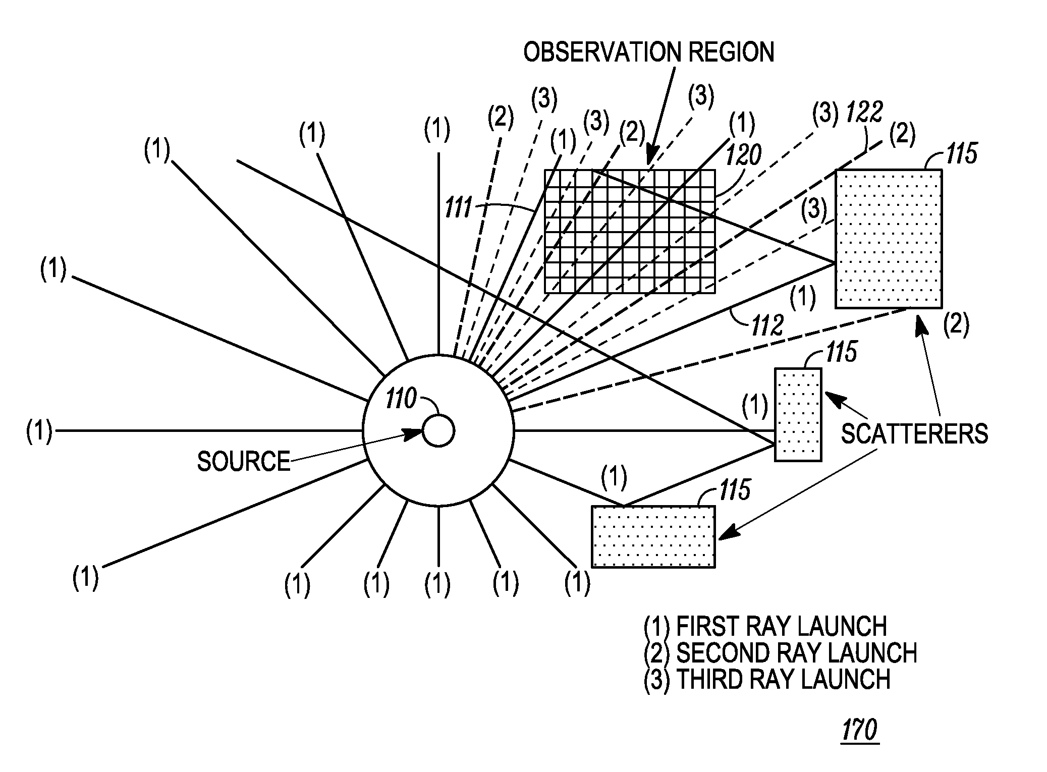
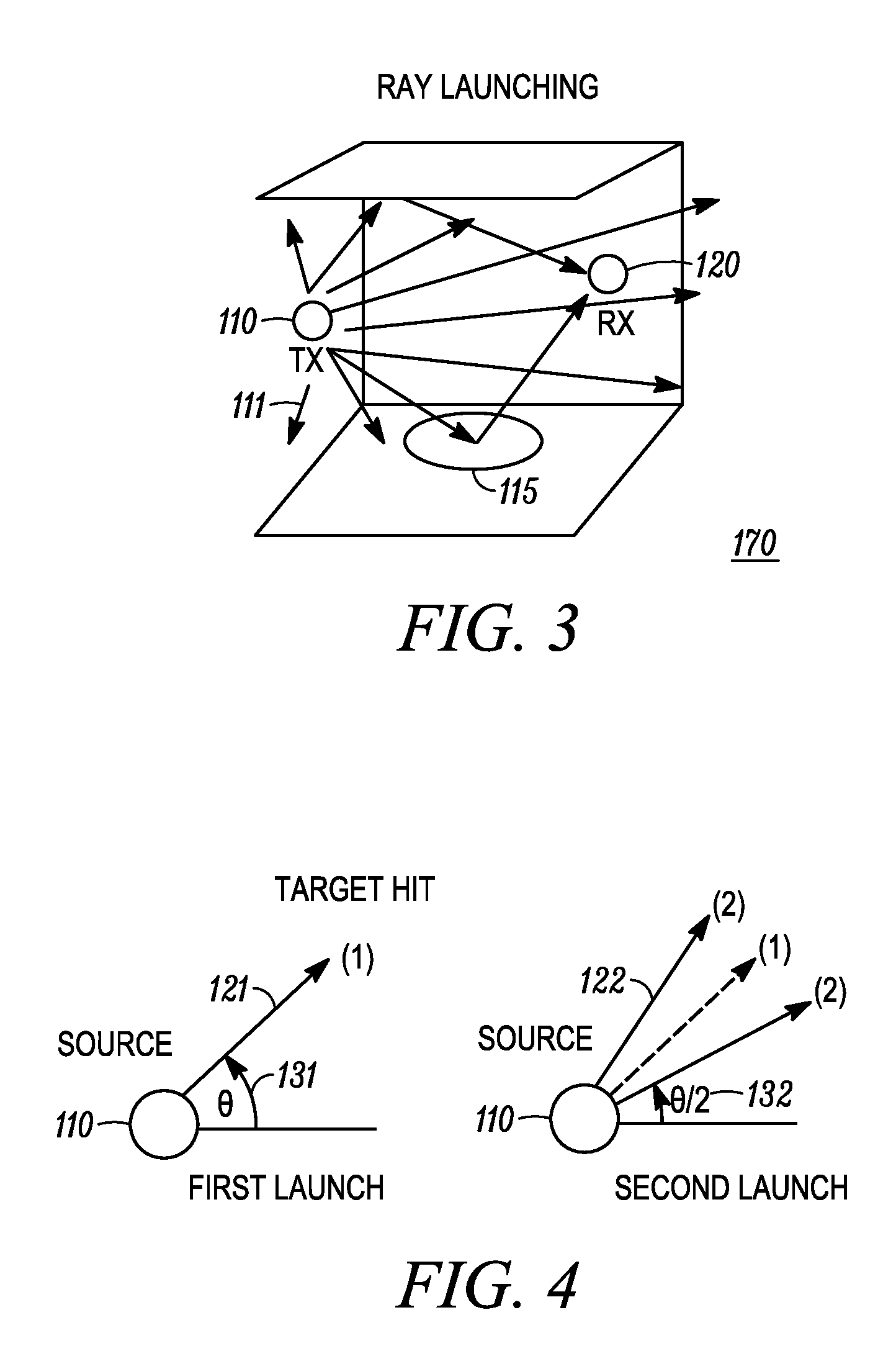
The invention is about a method and system for launching a plurality of rays in an environment and estimating their propagation. The technique of ray launching involves emitting a plurality of rays at an initial angle and then reducing their angle of emission to focus energy on a target. The system can include a transmitter for launching the rays and a receiver for receiving the rays and reflection rays from the environment. The transmitter can adjust the angle of emission for each ray to optimize energy concentration. The method can also involve eliminating pre-launch rays that do not have neighbors or have low tagging scores. The invention can improve the accuracy and efficiency of estimating signal propagation and energy propagation in a communication channel or medium.

Problems solved by technology

The hand-held radio and mobile device industry is constantly challenged in the market place for high audio quality products which provide good reception and coverage.
Signal strength and propagation can be compromised in environments having reflective objects.
Radio frequency signals transmitted in a cluttered environment can reflect off the objects causing interference.
This can lower the signal strength or introduce distortion in the received signal thereby deteriorating reception quality.
Moreover, due to reflections and initial directions, some of the propagating signals may never reach the mobile device.
These signals may not contribute to the reception at the mobile device.
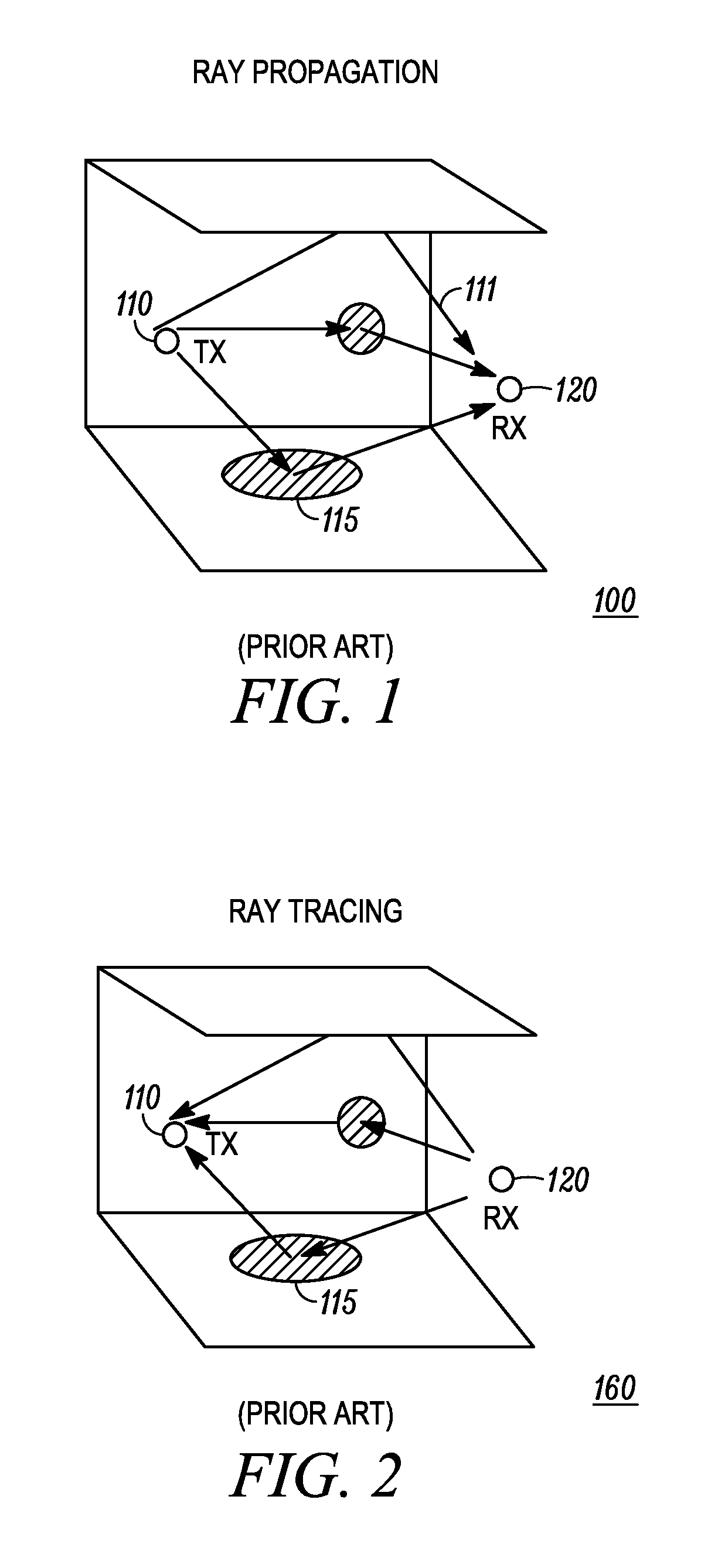
Ray tracing is a computationally expensive method for determining the number of rays that strike a target.
In particular, ray tracing has some significant disadvantages.
Ray tracing in three-dimensional environment can require complex databases having complex tracing structures that fail to converge.
Ray tracing cannot also adequately account for rounded or cylindrical surfaces in the environment.

Method used


Image

  • Method and system for adaptive ray launching
  • Method and system for adaptive ray launching
  • Method and system for adaptive ray launching

Examples


Embodiment Construction

[0031]While the specification concludes with claims defining the features of the embodiments of the invention that are regarded as novel, it is believed that the method, system, and other embodiments will be better understood from a consideration of the following description in conjunction with the drawing figures, in which like reference numerals are carried forward.

[0032]As required, detailed embodiments of the present method and system are disclosed herein. However, it is to be understood that the disclosed embodiments are merely exemplary, which can be embodied in various forms. Therefore, specific structural and functional details disclosed herein are not to be interpreted as limiting, but merely as a basis for the claims and as a representative basis for teaching one skilled in the art to variously employ the embodiments of the present invention in virtually any appropriately detailed structure. Further, the terms and phrases used herein are not intended to be limiting but rat...


PUM


Abstract

A system (170) and method (300) for ray launching is provided. The system can include a transmitter (110) for successively launching a plurality of rays, and a receiver (120) for receiving transmission rays and reflection rays. A controller (141) can be included for selectively adjusting an angular spacing and eliminating rays in successive launches to focus an energy on the receiver. A method (430) of terminating rays for reducing computational complexity is provided. A method (340) for ray weighting for increasing a computational speed of ray propagation is provided. In one aspect, a quality of service (108) can be determined at the receiver based on ray propagation.

Description

CROSS REFERENCE TO RELATED APPLICATIONS[0001]This application claims the benefit of U.S. Provisional Patent Application No. 60 / 868,068, filed Nov. 30, 2006, the entire contents of which are incorporated by reference herein.FIELD OF THE INVENTION[0002]The present invention relates to software, and more particularly, to modeling signal energy propagation.INTRODUCTION[0003]The hand-held radio and mobile device industry is constantly challenged in the market place for high audio quality products which provide good reception and coverage. Good coverage and reception are generally a function of signal propagation and signal strength. Signal strength and propagation can be compromised in environments having reflective objects. Radio frequency signals transmitted in a cluttered environment can reflect off the objects causing interference. This can lower the signal strength or introduce distortion in the received signal thereby deteriorating reception quality. Moreover, due to reflections an...

Claims


Application Information

Patent Timeline
Patent Type & Authority Patents(United States)
IPC IPC(8): H04W24/00
CPCH04B17/3912H04B7/0617
Inventor CORRAL, CELESTINO A.EMAMI, SHAHRIARSIBECAS, SALVADORSTRATIS, GLAFKOS
Owner GOOGLE TECH HLDG LLC
Learn More