Steering apparatus

a technology of steering apparatus and steering shaft, which is applied in mechanical apparatus, gearing details, transportation and packaging, etc., can solve the problems of steering stability deterioration and delay in steering operation, and achieve the effects of improving steering stability, effective suppression of deformation, and improving steering stability

Active Publication Date: 2011-06-14
NSK LTD
View PDF7 Cites 0 Cited by
  • Summary
  • Abstract
  • Description
  • Claims
  • Application Information

AI Technical Summary

Benefits of technology

[0047]In the steering apparatus according to the first aspect of the invention, two ribs configure the first rib for connecting the outer circumference of the hollow cylindrical portion to the vehicle attachment boss portion of the counter-pinion-side end. The two ribs are formed in a V shape so as to intersect each other at a position connected to the hollow cylindrical portion and to be away from each other at a position connected to the vehicle attachment boss portion of the counter-pinion-side end.
[0048]Accordingly, the first rib forms a closed loop by the vehicle attachment boss portion and the two ribs which are formed in a V shape. As a result, it is possible to effectively suppress the deformation of the vehicle attachment boss portion of the counter-pinion-side end in both the vertical direction and the longitudinal direction of the vehicle, and to thereby improve the steering stability.
[0049]In the steering apparatus according to the second aspect of the invention, the second rib is formed in the vicinity of the vehicle attachment boss portion of the counter-pinion-side end, in the upper outer circumference of the hollow cylindrical portion in the counter-pinion-side end.
[0050]Accordingly, the second rib assists the first rib to suppress the deformation of the vehicle attachment boss portion of the counter-pinion-side end in the vertical direction of the vehicle, and to thereby further improve the steering stability.
[0051]In the steering apparatus according to the third aspect of the invention, the third rib is formed in the vicinity of the vehicle attachment boss portion of the counter-pinion-side end, in the lower outer circumference of the hollow cylindrical portion in the counter-pinion-side end.
[0052]Accordingly, the third rib assists the first rib to suppress the deformation of the vehicle attachment boss portion of the counter-pinion-side end in the vertical direction of the vehicle, and to thereby further improve the steering stability.

Problems solved by technology

However, in such a technique in which the steering gearbox is attached to the vehicle frame by interposing the elastic member therebetween, the steering gearbox moves by an elastic deformation amount of the elastic member before the rack shaft moves at the time a pinion engaging with a rack shaft starts to rotate, thereby causing a delay of the steering operation.
As a result, a problem arises in that the steering stability deteriorates.

Method used


Image

  • Steering apparatus
  • Steering apparatus
  • Steering apparatus

Examples


Embodiment Construction

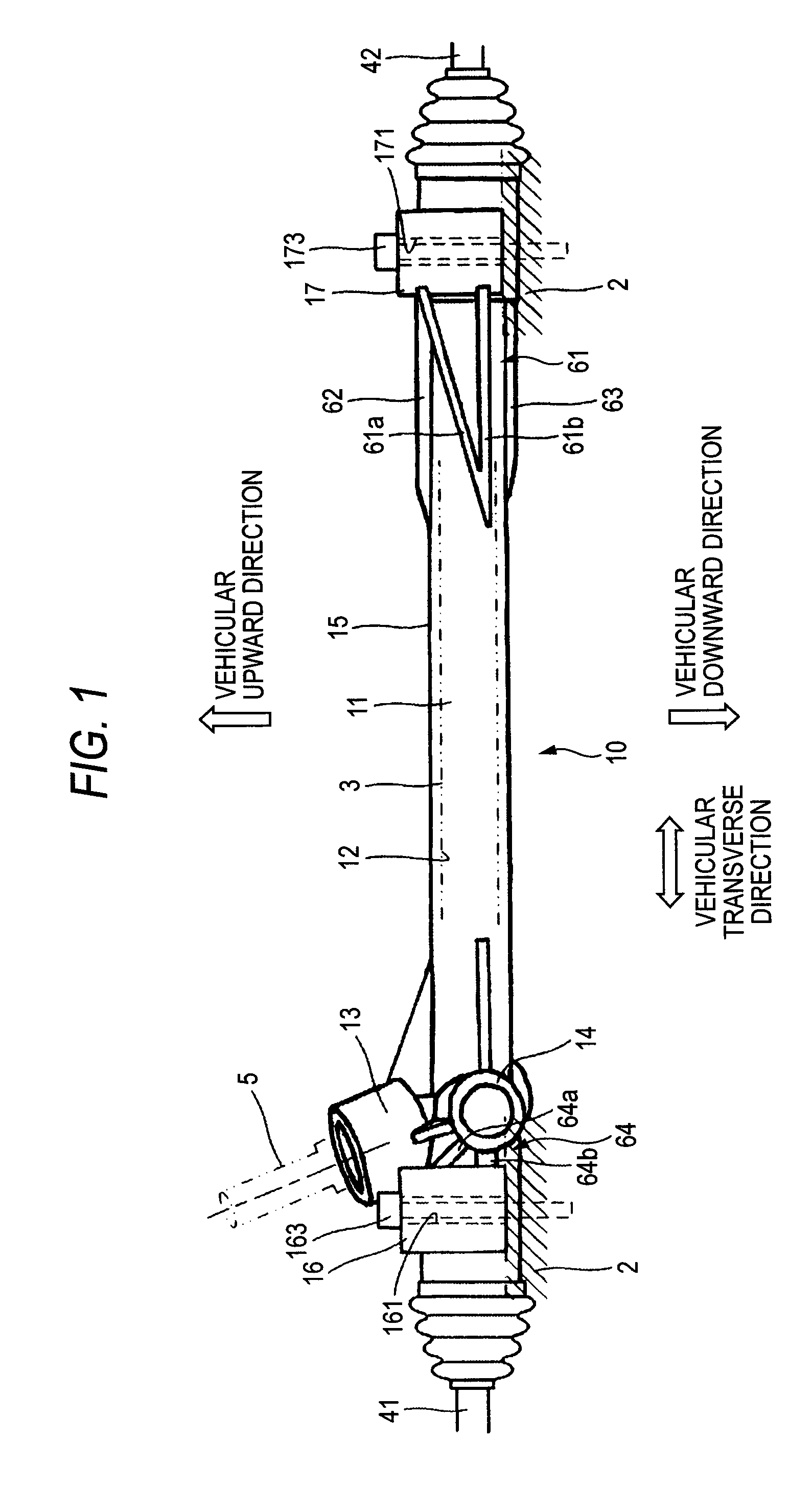
[0083]Hereinafter, an embodiment of the invention will be described with reference to the accompanying drawings. FIG. 1 is a front view illustrating a main part of a steering gearbox of a steering apparatus according to an embodiment of the invention. As shown in FIG. 1, a steering gearbox 1 according to the embodiment of the invention is attached to a vehicle frame 2 such as a front sub-frame. In FIG. 1, the upward direction is referred to as an vehicular upward direction, and the downward direction is referred to as a vehicular downward direction. In FIG. 1, the transverse direction is referred to as a vehicular transverse direction. In FIG. 1, a direction perpendicular to a paper surface is referred to as a vehicular longitudinal direction.

[0084]A rack shaft 3 is slidably fitted to an inner circumference 12 of a hollow cylindrical portion 11 of the steering gearbox 1 in the transverse direction shown in FIG. 1. Tie rods 41 and 42 are connected to both ends of the rack shaft 3, an...


PUM


Abstract

Even when bending stress acts on a steering gearbox 1 about attachment holes 161 and 171 of vehicle attachment boss portions 16 and 17, deformation of the vehicle attachment boss portions 16 and 17 in both the longitudinal direction and the vertical direction of the vehicle becomes small since rigidity with respect to deformation in the vicinity of the vehicle attachment boss portions 16 and 17 in both the longitudinal direction and the vertical direction of the vehicle is large due to a first rib 61 to a fourth rib 64. Accordingly, it is possible to improve steering stability at the time a steering reaction force occurs.

Description

TECHNICAL FIELD[0001]The present invention relates to a steering apparatus, and more particularly, to a steering apparatus including a steering gearbox which has a hollow cylindrical portion for allowing a rack shaft to be slidably fitted to the inside thereof and which is attachable to a vehicle frame.BACKGROUND ART[0002]A steering gearbox receives a steering reaction force transmitted from a traveling wheel during a steering operation. For this reason, in order to absorb the steering reaction force, an elastic member such as a cylindrical rubber bush is interposed between a bolt and an attachment hole for attaching the steering gearbox to the vehicle frame.[0003]However, in such a technique in which the steering gearbox is attached to the vehicle frame by interposing the elastic member therebetween, the steering gearbox moves by an elastic deformation amount of the elastic member before the rack shaft moves at the time a pinion engaging with a rack shaft starts to rotate, thereby ...

Claims


Application Information

Patent Timeline
Patent Type & Authority Patents(United States)
IPC IPC(8): B62D3/12B62D5/22
CPCB62D3/12Y10T74/2186
Inventor KOJIMA, KAZUHIKOAMADA, SHINYA
Owner NSK LTD
Why Eureka
Try Eureka