Tire pressure monitoring system

a technology of tire pressure monitoring and monitoring system, which is applied in vehicle tyre testing, instruments, roads, etc., can solve the problems of increasing battery life, and achieve the effect of saving cost and complexity, and reducing the number of separate communication buses in the vehicl

Active Publication Date: 2011-06-07
MELEXIS TECH NV
View PDF8 Cites 4 Cited by
  • Summary
  • Abstract
  • Description
  • Claims
  • Application Information

AI Technical Summary

Benefits of technology

[0006]This provides a TPMS wherein the control unit is operable to determine which sensor unit is associated with which wheel without additional equipment or without being pre-programmed. Additionally, as this reduces the average distance of transmission from sensor unit to communicator unit, the sensor units can output lower power signals this leading to increased battery lifetime.
[0015]The communicator units may be mounted in or on the housing of the side view mirrors of the vehicle: if there is a single communicator unit, it is mounted in or on the housing of a side view mirror of the vehicle; if there is a pair of communicator units, they are mounted in or on the housing of each side view mirror of the vehicle. In such embodiments, the communicator units may share a communication bus with an actuation controller unit operable to control actuator means for adjusting the alignment of the side view mirrors. In this manner the number of separate communication buses required in a vehicle can be reduced. This results in cost and complexity savings for vehicle manufacturers. Preferably, the communicator unit is integrated into the same package as the actuation controller unit. The actuator means may be motors such as servo motors. Preferably the package further includes a potentiometer for determining the position of the actuator means and a microcontroller for controlling the actuators in response to signals received from the control unit.

Problems solved by technology

Additionally, as this reduces the average distance of transmission from sensor unit to communicator unit, the sensor units can output lower power signals this leading to increased battery lifetime.

Method used


Image

  • Tire pressure monitoring system
  • Tire pressure monitoring system
  • Tire pressure monitoring system

Examples


Embodiment Construction

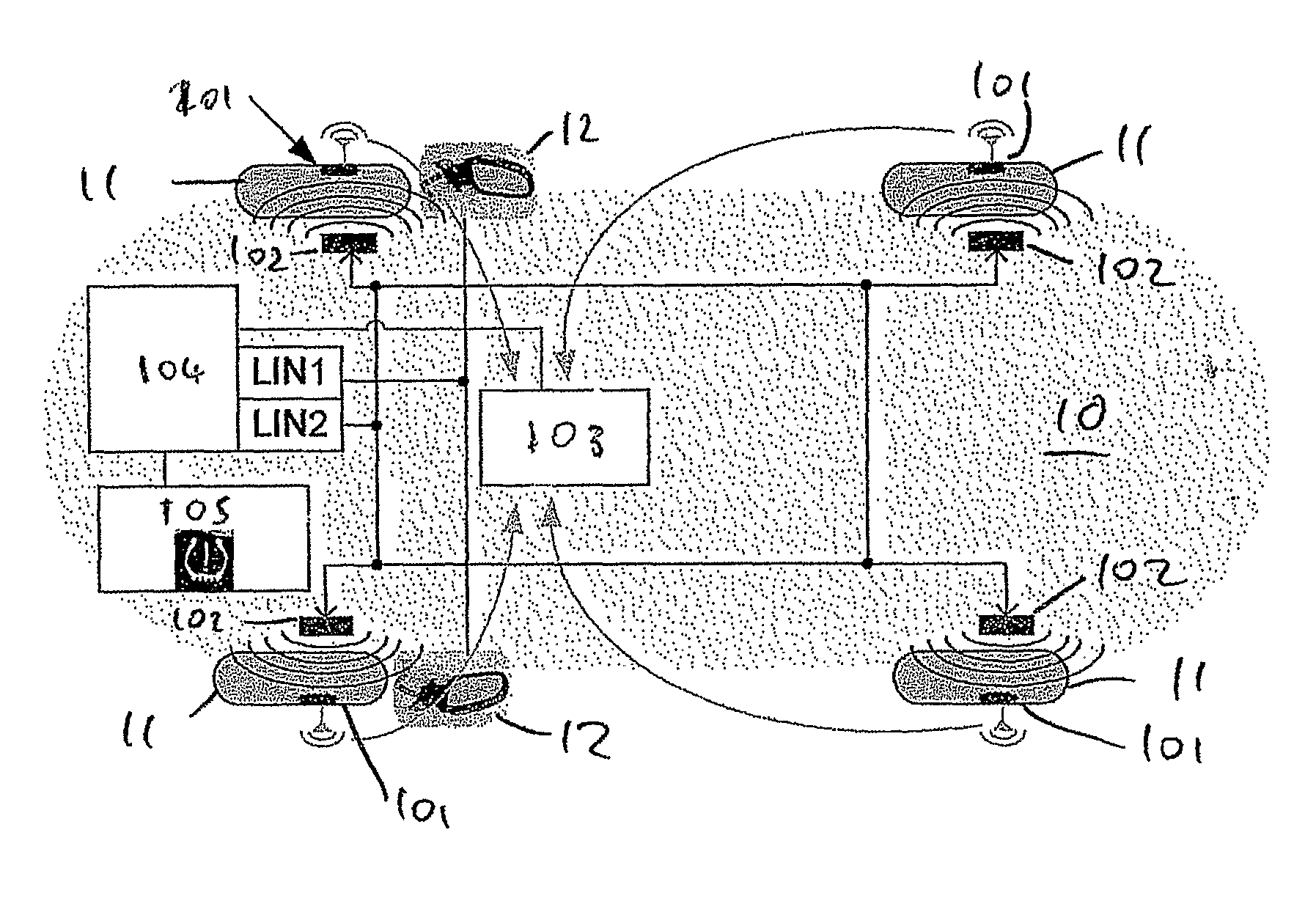
[0026]Referring now to FIG. 1, a known TPMS for a vehicle 10 comprises sensor units 101 mounted in each tire 11 of the vehicle 10 for monitoring the condition of the tires 11. A transmit / receive unit 102 is provided in the wheel well adjacent to each sensor unit 101 for communicating control signals between each sensor unit 101 and a control unit 104. Each sensor unit 101 is operable to output an RF signal indicative of the pressure in the tire 11. The output RF signal is received by a central receiver unit 103. The receiver unit 103 is usually mounted on the dashboard or on the roof of the vehicle and is connected to the control unit 104.

[0027]The control unit 104 is connected to a display unit 105 operable to process signals received from each sensor unit 101 and output and to cause the display unit 105 to output a suitable indication of the condition of each tire 101. In some embodiments, the display unit 105 may only output an indication if the condition of one or more of the ti...


PUM


Abstract

Tire pressure monitoring system for a vehicle includes sensor units mounted in each tire of the vehicle, each sensor unit being operable to output an RF signal indicative of the pressure in the tire in which it is mounted; a pair of communicator units for receiving signals from said sensor units, said pair of communicator units being provided at different locations on the vehicle; and a control unit connected to said communicator units wherein said control unit is operable to determine which sensor unit is associated with which tire by monitoring the strength of the RF signal received from each respective sensor unit by each communicator unit.

Description

BACKGROUND[0001]The present invention relates to a tire pressure monitoring system.[0002]Many modern vehicles incorporate tire pressure monitoring systems (TPMS). Typically, these systems comprise: a plurality of individual pressure sensor units, one mounted in each tire, each sensor unit operable to output an RF signal indicative of the pressure in the tire and a central control unit for monitoring the output of said sensor units. Typically, such systems are implemented with dedicated transmit / receive units for each sensor unit provided in each wheel well and connected to the control unit via a dedicated network such as a LIN bus. These transmit / receive units allow the control unit to communicate with and identify each sensor unit and thus determine which sensor unit is associated with which tire.[0003]Typically an additional central receiver unit is provided for receiving signals indicative of the pressure in each tire from each sensor unit. As a single centrally mounted receiver ...

Claims


Application Information

Patent Timeline
Patent Type & Authority Patents(United States)
IPC IPC(8): G01M17/02B60C23/04B60R1/12
CPCB60C23/0416B60C23/0418B60R1/12B60C23/0444B60R2001/1215
Inventor LEMAN, DIRK
Owner MELEXIS TECH NV
Why Eureka
Try Eureka