
Environmental enclosure for vehicle property testing

a technology for environmental enclosures and vehicles, applied in vehicle testing, engine testing, structural/machine measurement, etc., can solve the problems of reducing affecting the reliability of the testing facility, and affecting so as to reduce the amount of time, improve the overall efficiency of the testing facility, and reduce the amount of floor space

Active Publication Date: 2011-06-07
GM GLOBAL TECH OPERATIONS LLC
View PDF15 Cites 8 Cited by
  • Summary
  • Abstract
  • Description
  • Claims
  • Application Information

AI Technical Summary

Benefits of technology

[0007]The present invention offers full environmental testing capabilities, which can be performed in fueled engine or powertrain test cells without the limitations incurred by the use of a rigid climatic enclosure or a dedicated environmental test cell. The environmental enclosures of the present invention require significantly less floor space than prior art climatic test chambers, and reduce the amount of time required to run non-ambient temperature testing, appreciably improving the overall efficiency of the testing facility. The present invention also allows for off-line temperature soaking of vehicle test properties (e.g., engine, transmission, engine and transmission assembly, full powertrain, etc.), freeing up valuable testing equipment. In addition, the environmental enclosures of the present invention offer realized reductions in initial build and setup costs, as well as maintenance expenses. Finally, the design of the present invention offers a much more operator-friendly work environment than prior art facilities.
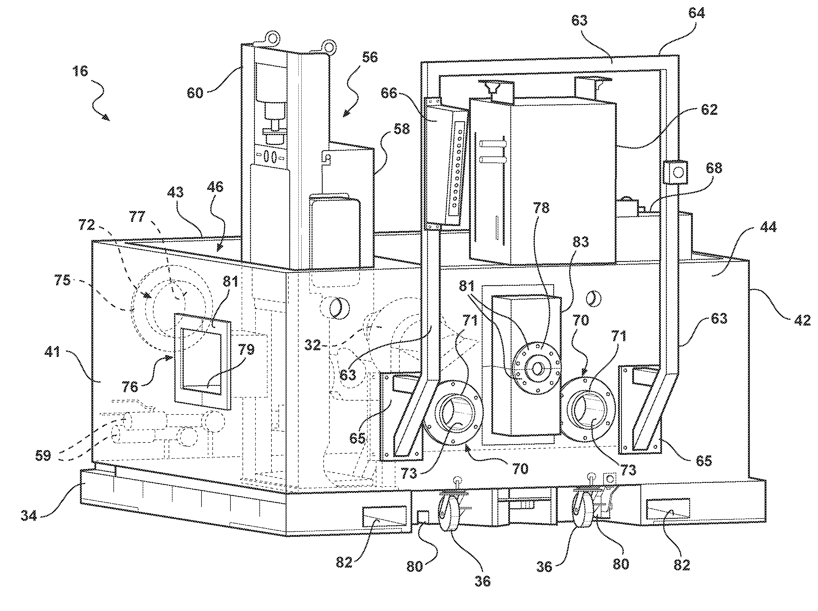
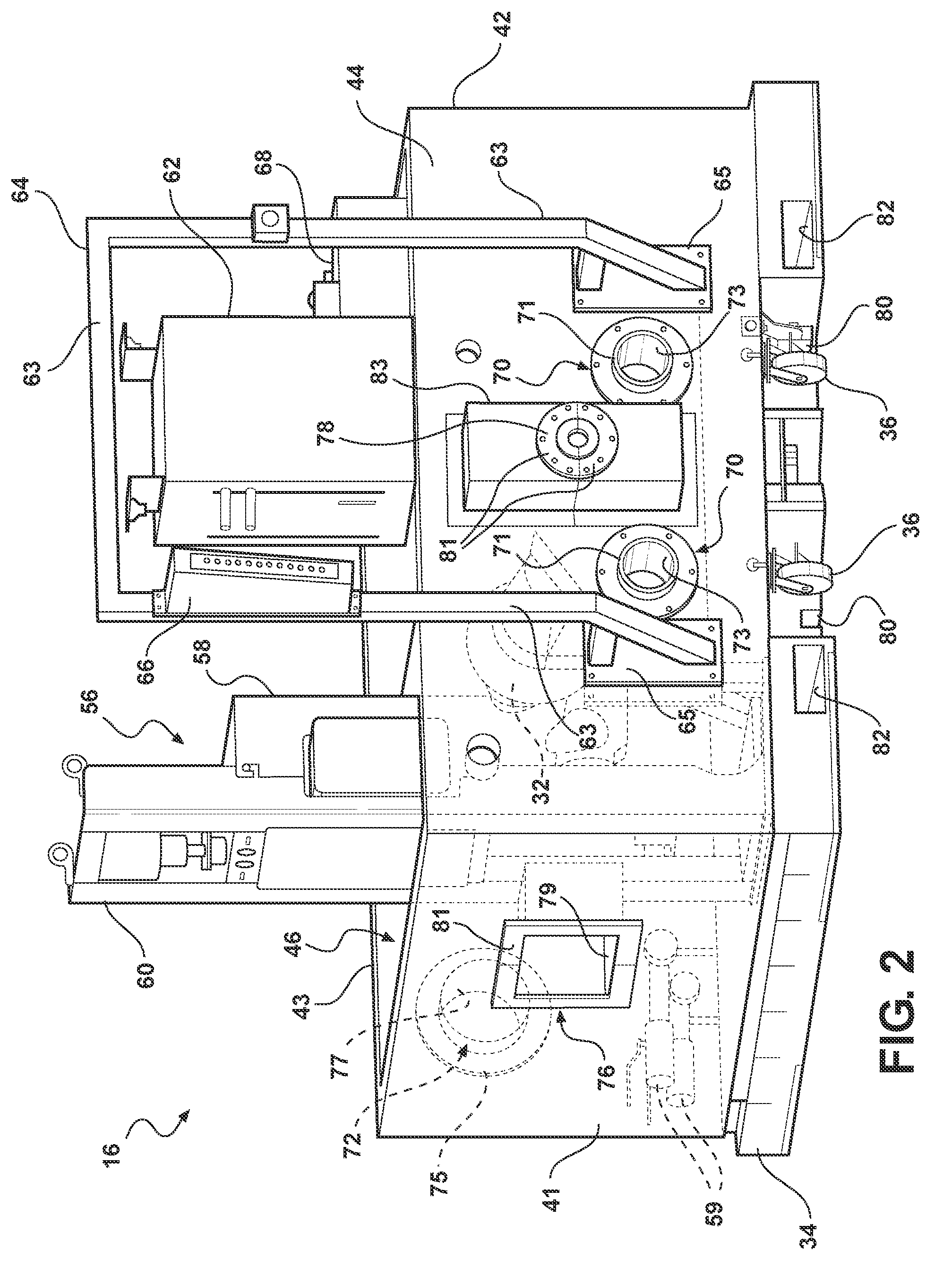
[0016]As part of another aspect of this particular embodiment, the movable pallet assembly includes a base plate with a plurality of sidewalls that are attached thereto, and project therefrom to surround the test property. At least one of the sidewalls defines a utility penetration that extends therethrough. Each utility penetration is configured to provide an access port between the pallet assembly and testing componentry external thereto when the flexible cover is attached to the movable pallet assembly. The movable pallet assembly preferably includes a plurality of support elements that are repositionably attached to the base plate. The support elements are configured to mate with, support and accurately align the test property. The base plate also includes one or more elongated channels that are configured to engage with the test site and thereby locate and align the movable pallet assembly relative to the flexible cover for subsequent attachment thereto.

Problems solved by technology

Rigid testing facilities in current use suffer various practical drawbacks.
In the first place, prior art environmental testing chambers are generally limited to a single, definitive use, which often ties up precious space and testing equipment.
This, in turn, causes a considerable lengthening of the times required to carry out the tests, which reduces the overall efficiency of the testing facility.
Secondly, the testing room itself creates a less than optimal working environment for operators who need to setup and break down the test property before and after soaking at extreme temperatures.
Third, rigid environmental enclosures tend to be very large, and are not easily adaptable to new testing equipment, procedures, and test property configurations.
Lastly, current production specialized climatic test chambers are very expensive, both in initial build and setup as well as maintenance costs.

Method used


Image

  • Environmental enclosure for vehicle property testing
  • Environmental enclosure for vehicle property testing
  • Environmental enclosure for vehicle property testing

Examples


Embodiment Construction

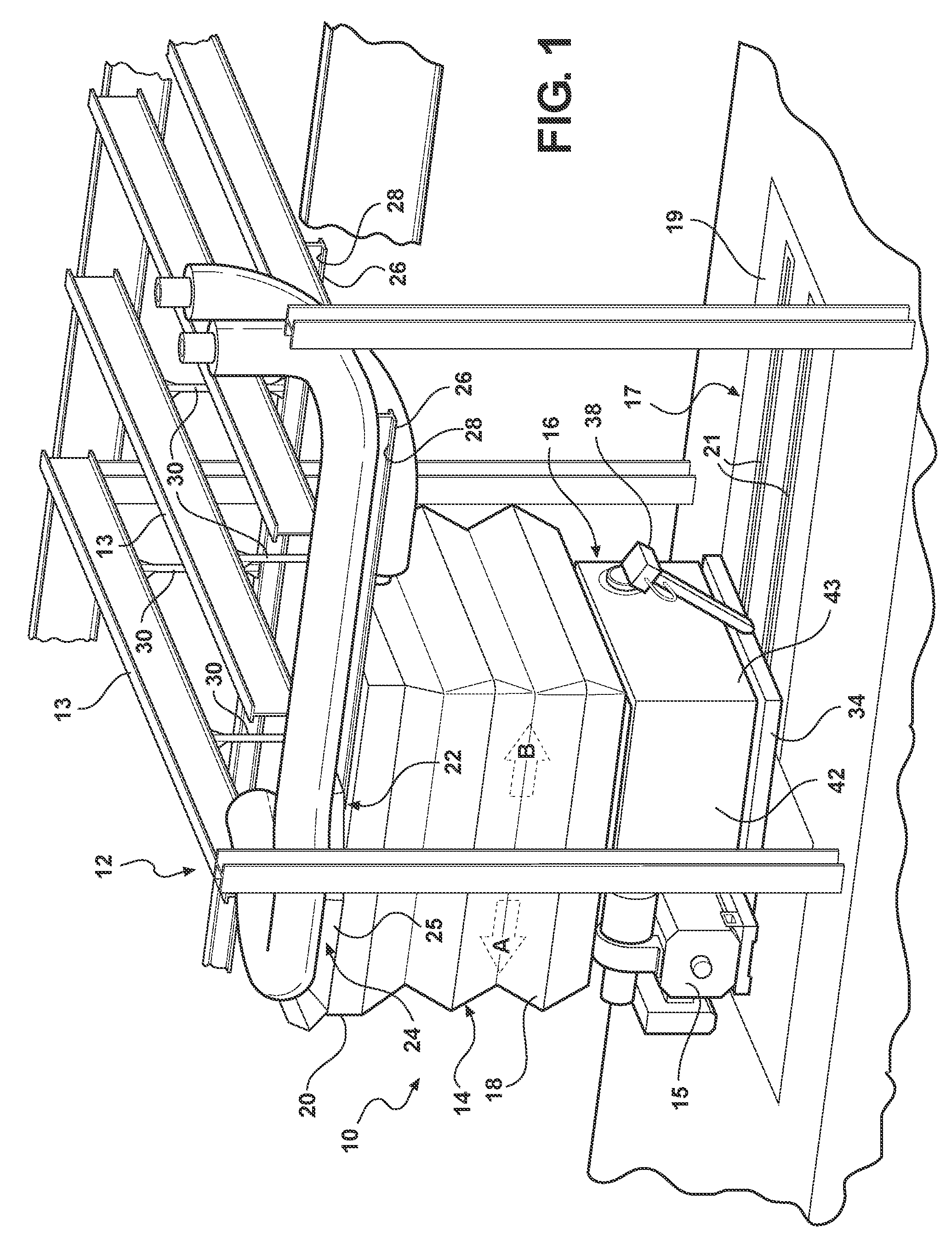
[0028]Referring to the drawings, wherein like reference numbers refer to like components throughout the several views, FIG. 1 illustrates a flexible environmental test enclosure in accordance with a preferred embodiment of the present invention. The particular arrangement shown in FIG. 1 is provided merely for exemplary purposes. As such, the general layout and orientation of the constituent components of the flexible environmental test enclosure may be modified within the scope of the appended claims. To this regard, it should be appreciated that the adjectives used herein to specify spatial relationships of the constituent components, such as forward, rearward, horizontal, vertical, upper, lower, etc., indicate spatial relationships as they exist with respect to their intended orientations relative to the test site when operatively oriented therein. Nevertheless, the spatial relationships specified may be varied within the scope of the claims appended hereto. Finally, the drawings...


PUM


Abstract

An environmental test enclosure for modifying the temperature of a vehicle test property is presented. The enclosure includes a movable pallet assembly that is operable to deliver the test property to and from the property test site. The movable pallet assembly includes a base plate that is configured to attach to and support the test property thereon. A plurality of sidewalls project upward from the base plate to surround the test property. A flexible cover is mounted to the overhead structure of the test site, and configured to transition between an open position, in which the cover is in a raised and generally folded state, to a closed position, in which the cover is in a lowered state and attachable to the pallet assembly. The flexible cover cooperates with the movable pallet assembly when attached thereto to define an enclosed and substantially thermally insulated space around the test property.

Description

TECHNICAL FIELD[0001]The present invention relates generally to test cells for motor vehicles, and more particularly to environmental enclosures for vehicle property testing.BACKGROUND OF THE INVENTION[0002]As part of the ongoing objective of automotive manufacturers to produce high quality automobiles, every effort is made to ensure that new vehicles are quiet and operate correctly under normal operating conditions. In the field of motor vehicles, and particularly in the production of internal combustion engine assemblies, testing is normally done on a large scale basis. Testing is traditionally performed in a continuous manner on a variety of different types of engines at any one point in time at a single test facility. Test engineers and technicians often use a dressing area which allows the engines to be prepped or “dressed” prior to entering the engine test cell. As a further means of facilitating the testing process and minimizing the down time of the test room, a test operato...

Claims


Application Information

Patent Timeline
Patent Type & Authority Patents(United States)
IPC IPC(8): G01M17/00G01M99/00
CPCG01M15/02
Inventor GUSHMAN, RICHARD W.WOMACK, MARK D.GUNNELS, DAVID J.
Owner GM GLOBAL TECH OPERATIONS LLC
Learn More