Universal plug adapter
- Summary
- Abstract
- Description
- Claims
- Application Information
AI Technical Summary
Benefits of technology
Problems solved by technology
Method used
Image

Examples
Embodiment Construction
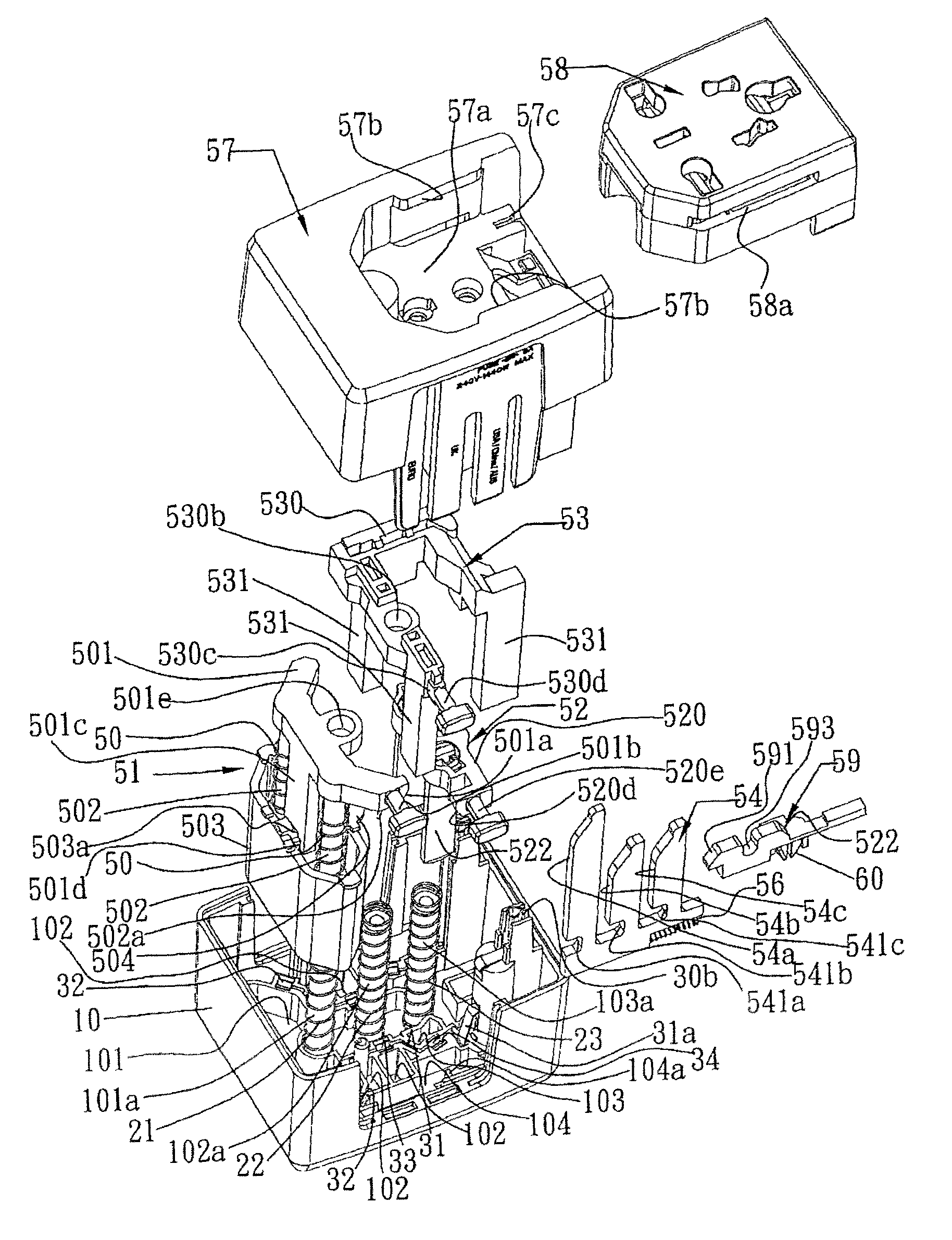
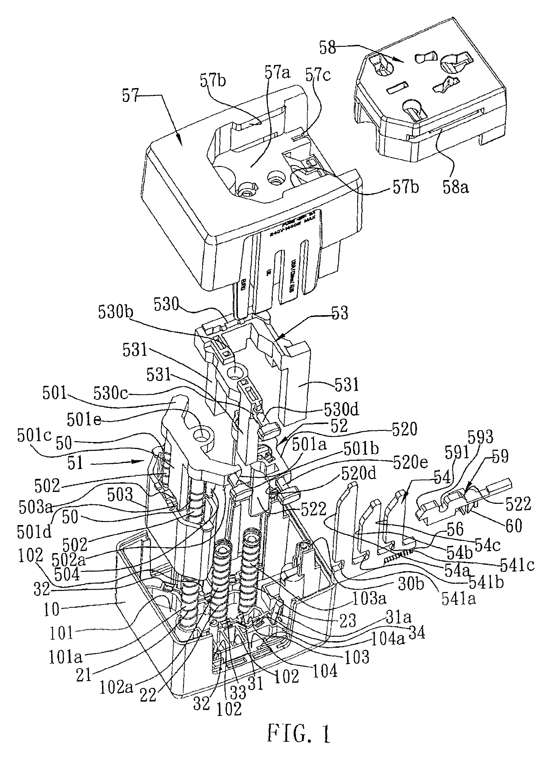
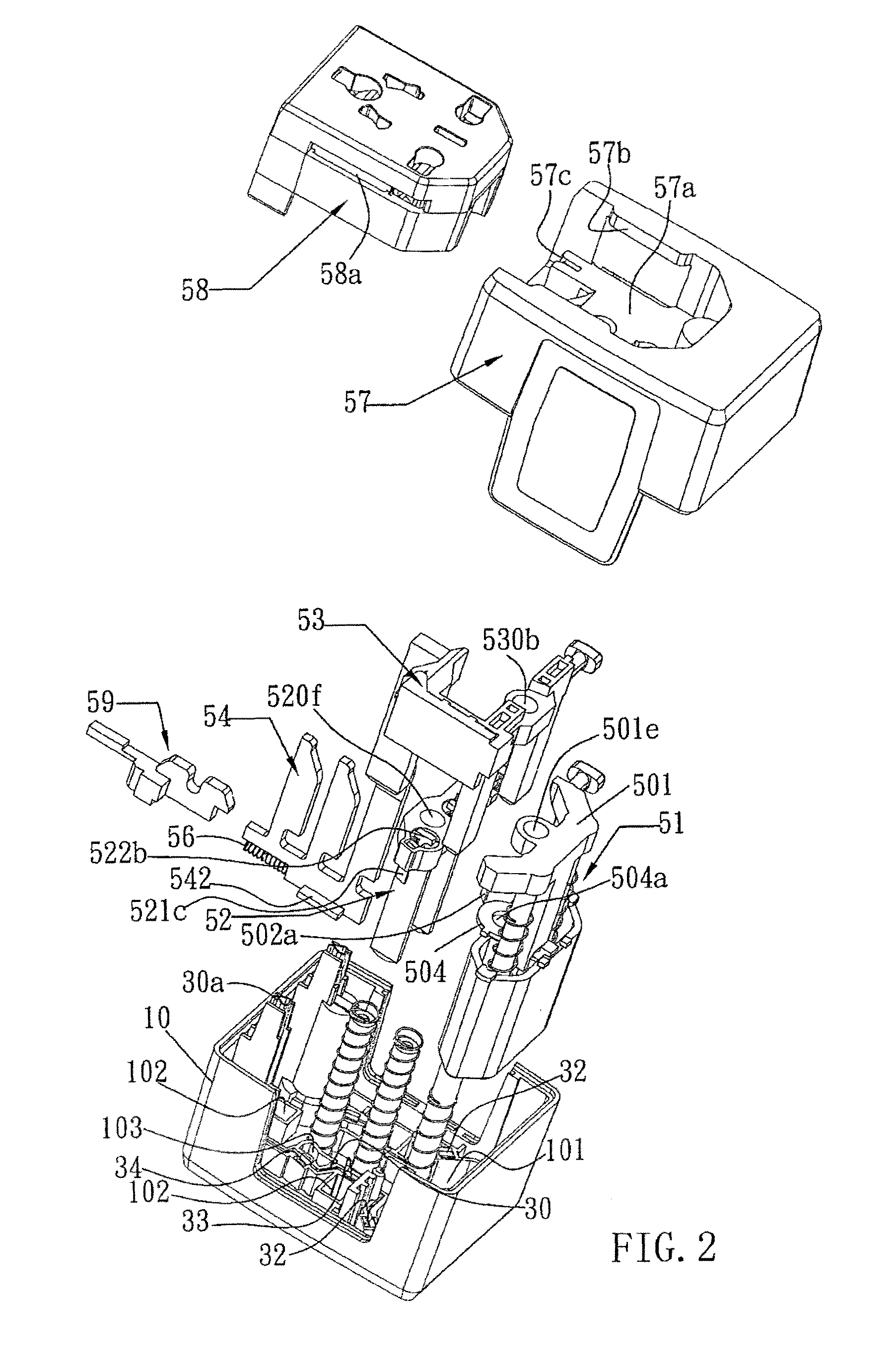
FIGS. 1 and 2 are exploded views of a universal plug adapter according to the present invention. The universal plug adapter comprises the following components.
A lower shell unit 10 (referring to FIG. 5) has primarily therein an A-terminal hole 101, B-terminal holes 102 and C-terminal holes 103, a movable rail portion 104 at one side thereof with a protrusion 104a, a plurality of posts 101a, 102a and 103a mounted therearound with springs 21, 22 and 23, and two metal conducting plates 30 and 31 inlaid and extending along edges of the A-terminal hole 101, B-terminal holes 102 and C-terminal holes 103. The two metal conducting plates 30 and 31 are formed with conducting clamps 32, 33 and 34 near the edges of the A-terminal hole 101, B-terminal holes 102 and C-terminal holes 103. In addition, the metal conducting plate 30 has one end bent upward to form a power-source clamp 30a, and the other metal conducting plate 31 has one end bent upward to form an abutting portion 31a to abut agains...
PUM
 Abstract
Description
Claims
Application Information
 - R&D
- Intellectual Property
- Life Sciences
- Materials
- Tech Scout
- Unparalleled Data Quality
- Higher Quality Content
- 60% Fewer Hallucinations
Browse by: Latest US Patents, China's latest patents, Technical Efficacy Thesaurus, Application Domain, Technology Topic, Popular Technical Reports.
© 2025 PatSnap. All rights reserved.Legal|Privacy policy|Modern Slavery Act Transparency Statement|Sitemap|About US| Contact US: help@patsnap.com