
Automatically locking high security holster

a high-security, locking mechanism technology, applied in the direction of money bags, transportation and packaging, arm wearables, etc., can solve the problems of difficult limit the ability to draw a pistol from a conventional holster, etc., and achieve the effect of increasing the speed of pistol drawing

Active Publication Date: 2011-05-31
RASSIAS JOHN N
View PDF38 Cites 37 Cited by
  • Summary
  • Abstract
  • Description
  • Claims
  • Application Information

AI Technical Summary

Benefits of technology

"The present invention provides an automatic self-locking, high security holster with a locking system that allows a law enforcement officer to protect against dangerous aggression through assurance that the locking system is extremely difficult to override by a perpetrator attempting to grab the pistol. The security holster and locking system provide a standby weapon platform, increased pistol drawing speed, and added pistol security through the use of one hand in a gross motor movement. The design of the security holster and locking system offers significant improvement in both on-duty and off-duty pistol retention and provides a level of safety unobtainable with conventional holsters. The security holster can be worn in a cross draw position, shoulder holster position, or thigh holster position with the same high levels of speed, access, and safety."

Problems solved by technology

The significant amount of equipment carried on an officer's duty belt and the constraints provided by the configuration of the driver's seat limit the ability to draw a pistol from a conventional holster in an upward drawing motion.
The constraints of wearing body armor and safety belts while driving makes difficult the ability to draw a pistol in an upward motion to clear the three- to five-inch drawing action without telegraphing the draw to a possible opponent.

Method used


Image

  • Automatically locking high security holster
  • Automatically locking high security holster
  • Automatically locking high security holster

Examples


Embodiment Construction

[0055]For purposes of the description hereinafter, spatial or directional terms shall relate to the invention as it is oriented in the drawing figures. However, it is to be understood that the invention may assume various alternative variations, except where expressly specified to the contrary. It is also to be understood that the specific apparatus illustrated in the attached drawings, and described in the following specification, is simply an exemplary embodiment of the invention. Hence, specific dimensions and other physical characteristics related to the embodiments disclosed herein are not to be considered as limiting, unless otherwise indicated.

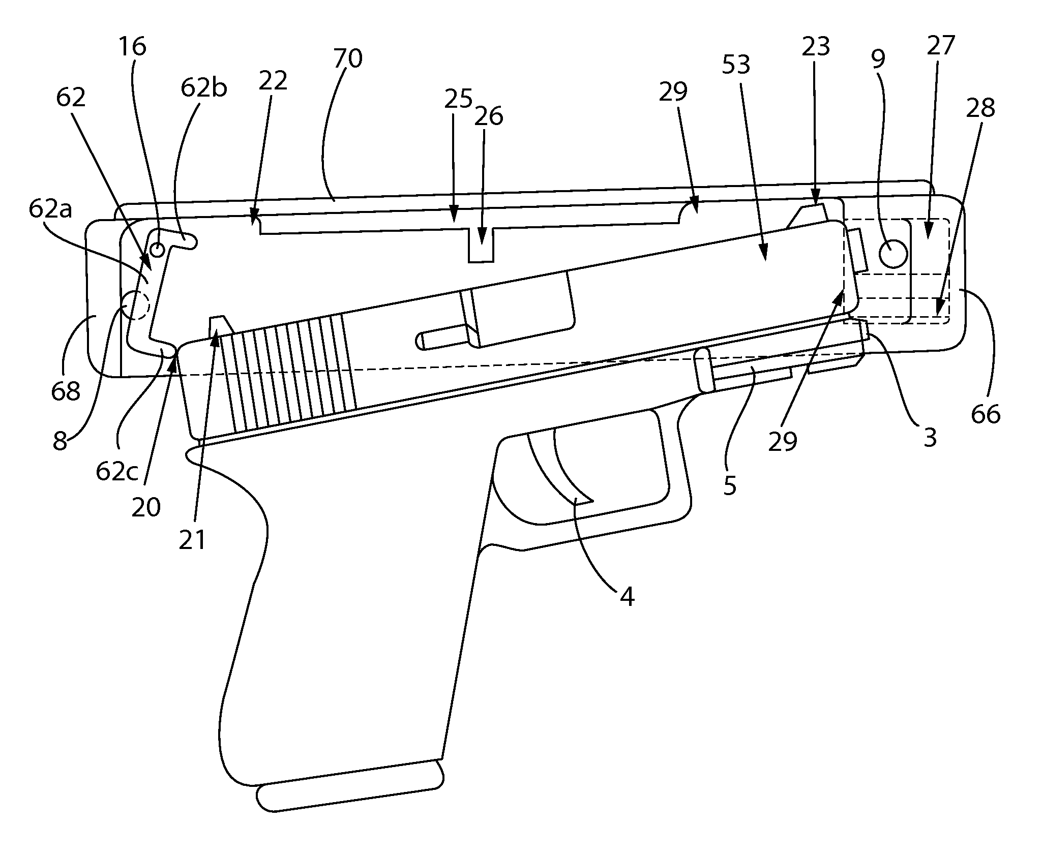
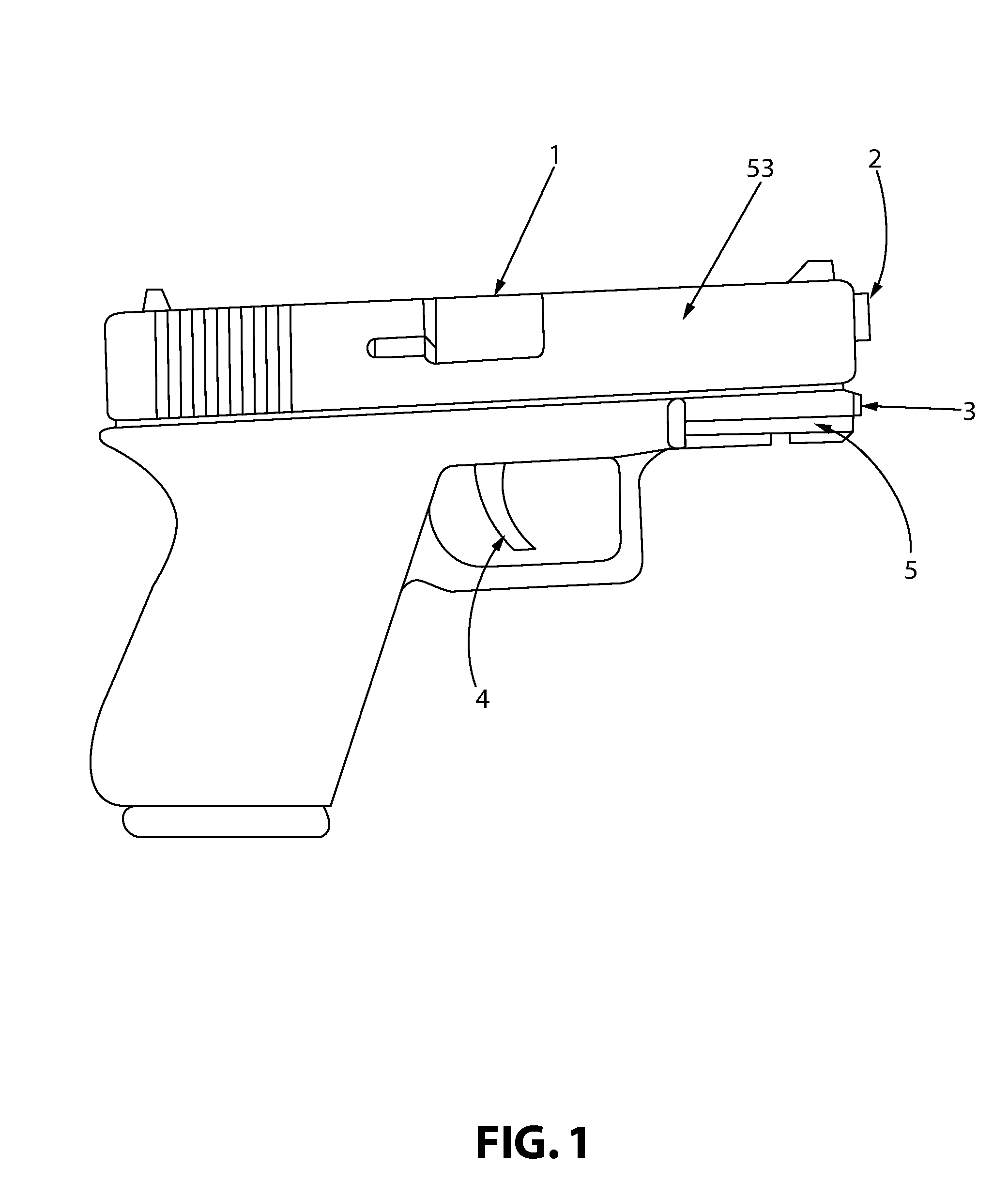
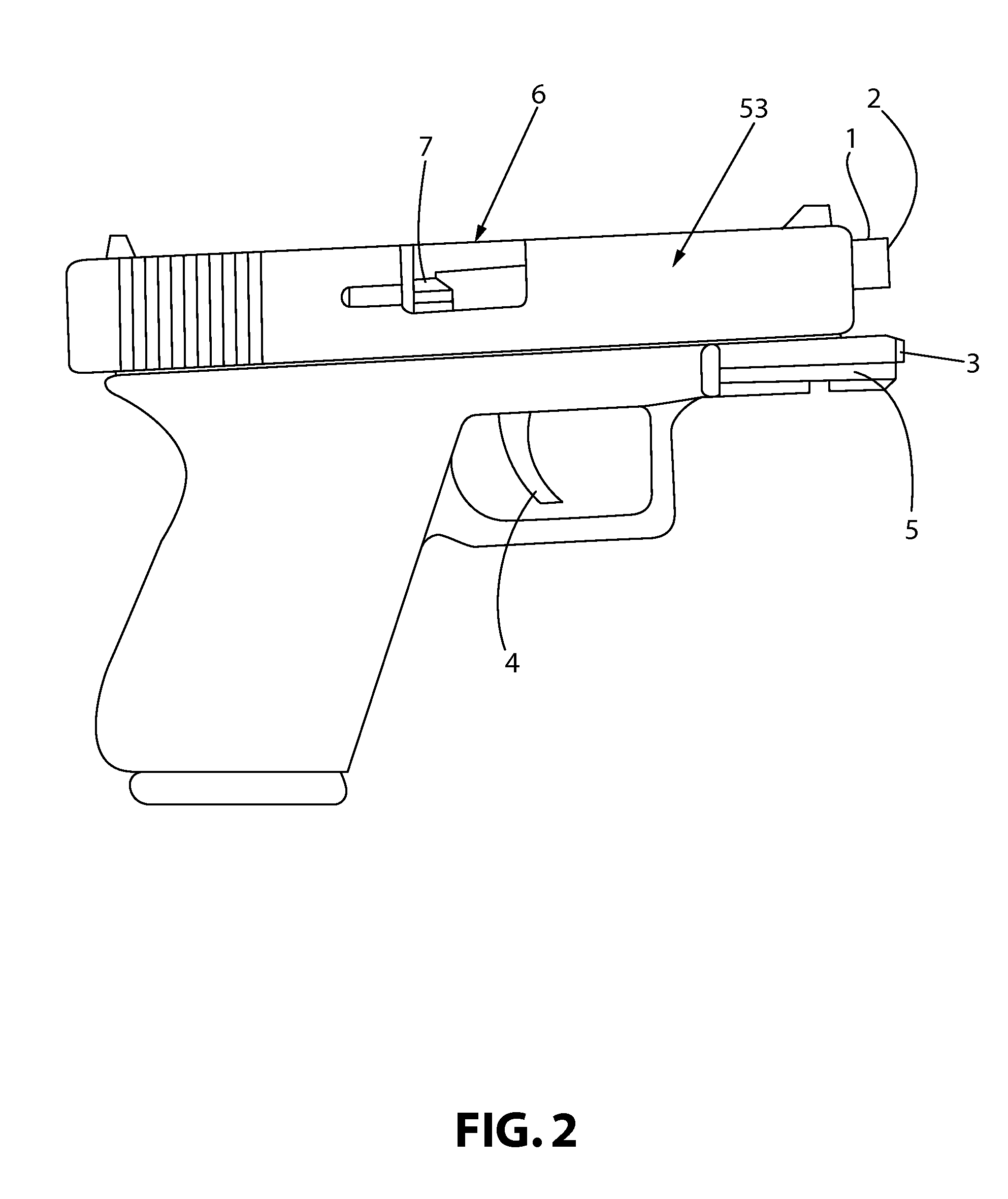
[0056]In reference to the disclosure of the invention throughout FIGS. 1-18b, similar references to similar parts are used uniformly throughout the disclosure of a security holster 60 including a holster body 10 and a securing lever 62 connected by a pivot pin 16 and a guide pin 64 to a locking safety lever 12. The securing lever 62 and...


PUM


Abstract

A holster for securing a pistol having a barrel with a chamber, a muzzle, a slide having a front and rear portion, includes (a) an open-bottom enclosure sized to accommodate the slide, wherein a cavity defined in a front portion of the enclosure is sized to receive the muzzle but not allow the slide to enter therein; (b) a securing member pivotally attached within the enclosure near a rear portion thereof and shaped to correspondingly mate with a rear portion of the slide; (c) a lever disposed externally to the enclosure and attached via a connecting member to the securing member; (d) a spring disposed between an interior surface of the enclosure and the securing member; and (e) a protuberance extending from the interior surface of the enclosure and sized to be received into the chamber when the pistol is secured within the enclosure.

Description

CROSS REFERENCE TO RELATED APPLICATIONS[0001]This application claims the benefit of U.S. Provisional Patent Application No. 60 / 678,504, filed May 6, 2005, entitled “Automatically Locking High Security Holster,” the contents of which are incorporated herein by reference.BACKGROUND OF THE INVENTION[0002]1. Field of the Invention[0003]The present invention relates to a high security holster with a locking mechanism and methods of use thereof.[0004]2. Description of Related Art[0005]Over the past several years, law enforcement personnel have been targeted by highly aggressive members of the citizenry throughout the day-to-day duties of law enforcement personnel. The media broadcasts weekly violent attacks on law enforcement officers, which oftentimes ends in severe wounding or deaths of the officers and innocent bystanders. The term “gun grab” has become widely understood. For example, the unfortunate events of a successful gun grab in the year 2005 from an officer in a municipal courth...

Claims


Application Information

Patent Timeline
Patent Type & Authority Patents(United States)
IPC IPC(8): F41C33/02
CPCF41C33/0236F41C33/0281F41C33/0263Y10S224/912
Inventor RASSIAS, JOHN N.
Owner RASSIAS JOHN N
Learn More