Optical multiwavelength window contamination monitor for optical control sensors and systems

a technology of optical control sensors and optical control sensors, applied in the field of optical instruments, can solve the problems of not only compromising the functional performance of optical instruments, but also impact, and instruments may yield inaccurate readings, etc., to achieve the effect of reducing the impact of the following factors

Active Publication Date: 2011-05-24
JOHN FLUKE MFG CO INC
View PDF6 Cites 11 Cited by
  • Summary
  • Abstract
  • Description
  • Claims
  • Application Information

AI Technical Summary

Benefits of technology

[0013]In another aspect, the device has a housing, a light source positioned inside the housing, and a crown positioned outside the housing and on the opposite side of the light source. In another aspect, the curvature of the crown is suitable for diffusing light incident on the internal surface of the crown in the direction of the window facing the internal surface of the crown and surrounded by the rim of the crown. In one embodiment, the crown is made of metal, plastic, or glass. In another embodiment, the crown has an internal machined, chemically etched or sandblasted surface. In another embodiment, the internal surface is coated to achieve a diffused or partially diffused characteristics of the reference source. In another embodiment, the crown is made of glass with a coating applied to the external side to achieve diffused or partially diffused characteristics of the reference source. In another embodiment, the external side of a glass crown is made rough in order to improve its diffusive characteristic and to facilitate cleaning of the internal, smooth surface of the crown.
[0014]In another aspect, if an instrument produces a target image, the geometry of the external reflector can include a multiplicity of smaller reflectors (ribs) which will allow the instrument to achieve sufficient reflection and yet will not completely block the field of view of the instrument. In case of an imaging instrument, this can also minimize the obstruction of peripheral vision of the optical instrument. In one embodiment, the crown is formed with a plurality of side reflectors. In another embodiment, the teeth of the crown are rectangular or rounded rectangular. In some embodiments, the crown has multiple teeth with crenellations selected in view of both the ability of the crown to diffuse light in the direction of the window and the possibility of restoring the peripheral view to a substantially complete state.
[0019]In some embodiments of the system and method for detecting contamination described herein, a ratio measurement at two selected wavebands replaces the absolute intensity measurement. In other words, these embodiments use a spectroscopic measurement at two predetermined spectral regions selected for the maximum sensitivity to a particular type of contamination. Because a system using multiple wavebands uses a relative change in the transmissivity of the window for two or more spectral regions rather than relying on an absolute measurement of intensity, the system may minimize the impact of the following factors: mechanical movement of the source / detector combination; optical misalignment between the source and the detector; contamination of the source and external reflectors; and temperature coefficients and drifts of the source and detector.

Problems solved by technology

These instruments may yield inaccurate readings if dust, debris, or other foreign materials contaminate this front window.
In case of the safety- and process-critical applications, these inaccuracies may expose an operator to some dangerous conditions.
In the case of process control applications, front window contamination will not only compromise the functional performance of the optical instrument but also impact various process control functions which rely on the accuracy of the instrument.
The problem of window contamination is particularly prevalent in those industrial environments where dust, soot, water or oil droplets are present as a part of an operating environment and / or generated as a by-product of the process requiring optical measurements.
Because window contamination is unavoidable in these environments, operators and technicians require reliable methods of detecting contamination in a timely fashion.
Some level of window contamination will directly impact the accuracy of such instruments, thus resulting in incorrect temperature readings and inaccurate control functions.
Clearly, this type of inspection takes a significant amount of time and requires a human presence in close proximity to the process control area.
Further, the level of skill and diligence of a particular operator may introduce additional uncertainties and even errors into the process of detecting, and cleaning of window contaminants.
Still further, because optical process control and monitoring devices are frequently positioned in places that may be extremely dangerous and harmful to an operator, it is highly desirable to keep the process of inspection and cleaning of optical device windows to a minimum.
In addition to posing a high risk to human safety, window contamination and the related maintenance may be associated with high costs.
Similarly, petroleum processing plants and chemical plants extensively use optical instrumentation with windows or lenses susceptible to contamination.
Because most modern plants and factories operate twenty four hours a day, the accumulative cost of process stoppage and re-starting may cost hundreds of thousands, if not millions, of dollars.
Additionally, stoppage time may cause significant damage to partially processed materials and may render part of the output of a plant defective.
For example, if molten metal or metal alloy such as steel is allowed to cool down at an unexpected stage of the process, some of the metal may have to be discarded, thus raising the cost of optical window maintenance even higher.
However, this method cannot provide a complete coverage of the surface of the window, thus providing only a partial information regarding the condition of the window.
Furthermore, the accuracy of this method will be significantly impacted if the mirror itself is contaminated or partially covered by the dirt or debris.
Unfortunately, this approach also has some significant shortcomings.
In particular, the external illuminator obscures the optical path of the optical device.
Additionally, the external illuminator itself may accumulate dust particles or other forms of contamination.
Accurate and meaningful absolute intensity measurement is limited to various uncertainties and changes of both the reference source and the detector.
If the reference source is external to the body of the instrument, then one of the main uncertainties if the external source is also contaminated by the same dust.
However, this approach also provides only partial coverage of the window.
Similarly to the solution involving an illuminator suspended directly in front of the window, and an external mirror the fiber optic light pipe is also prone to contamination.
Moreover, the fiber optic tip is fragile and thus reduces the durability of the apparatus.
In general, the solutions known in the art share several additional limitations.
Specifically, all of the available methods and systems have high margins of error due to the potential changes in the environment and none of the solutions teaches an effective method of addressing these additional factors.
Because the spectral qualities of some of the elements used in these solutions vary with temperature and age, carrying out calculations related to the transmission of electromagnetic radiation with a high degree of accuracy becomes a relatively complicated task.
For example, the spectral qualities of a window of an optical device may be significantly influenced by the environmental factors and, if these changes are ignored, the detection of contaminants may not always be accurate.

Method used


Image

  • Optical multiwavelength window contamination monitor for optical control sensors and systems
  • Optical multiwavelength window contamination monitor for optical control sensors and systems
  • Optical multiwavelength window contamination monitor for optical control sensors and systems

Examples


Embodiment Construction

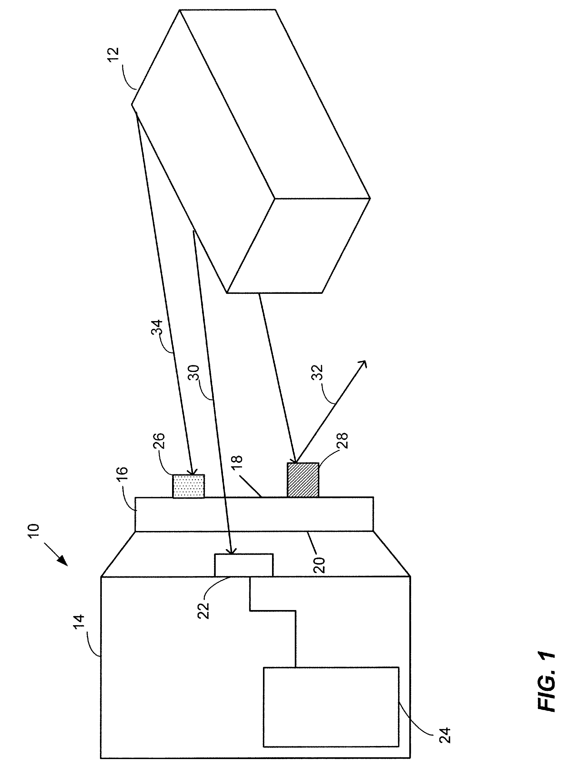
[0031]FIG. 1 is a schematic representation of an optical instrument or measuring device 10 remotely measuring the temperature of a body 12. The device 10 contains a housing 14, a transmissive pane or window 16 with a first (external) side 18 and a second (internal) side 20, and a light detector 22. Additionally, a controller 24 may be disposed inside the housing 14. In operation, the optical measuring device 10 detects electromagnetic radiation emanating from the body 12. More specifically, the detector 22 may generate a voltage signal indicative of the intensity of incident electromagnetic radiation and propagate the voltage signal to a processing unit such as the controller 24. However, the controller may be disposed outside the housing 14 and be communicatively coupled to the device 10 in a conventional way, such as via a copper wire, for example.

[0032]Under certain operating conditions, dust, debris, and other foreign particles may accumulate on the external side 18 of the windo...


PUM

PropertyMeasurementUnit
wavelengthsaaaaaaaaaa

Abstract

A foreign-particle detection system for use with an optical instrument having a transmissive window with a first side and a second side includes a radiation source to emit a radiation signal, a diffusing reflector to diffusively spread the radiation signal emitted by the radiation source over the first side of the transmissive window, a radiation detector to detect, at the second side of the transmissive window, the diffusively spread radiation signal transmitted by the transmissive window, and to generate a detected radiation signal based on the detected diffusively spread radiation signal, and a computation module communicatively coupled to the radiation detector to detect a presence of foreign particles on at least one of the first side or the second side of the transmissive window based on at least the detected radiation signal.

Description

CROSS REFERENCE TO RELATED APPLICATIONS[0001]This application claims benefit of the U.S. Provisional Application No. 60 / 948,662 entitled “Optical Multiwavelength Window Contamination Monitor for Optical Control Sensors and Systems,” filed Jul. 9, 2007, the disclosure of which is hereby expressly incorporated herein by reference.FIELD OF THE INVENTION[0002]The disclosure generally relates to optical instrumentation and, more particularly, to a system and method of detecting contamination of a transmitting path of an optical measuring device.DESCRIPTION OF THE RELATED ART[0003]Optical instrumentation is extensively used in various industrial, military, and commercial applications. Recent advances in the field of robotics have further spurred the proliferation of optical devices capable of detecting and processing various forms of electromagnetic radiation. In some applications, optical instruments may be designed to detect electromagnetic radiation in the visible optical range. In oth...

Claims


Application Information

Patent Timeline
Patent Type & Authority Patents(United States)
IPC IPC(8): G01N21/00
CPCG01N21/94G01N2021/945G01N2021/157
Inventor SHUBINSKY, GARYPARIS, SAM
Owner JOHN FLUKE MFG CO INC
Why Eureka
Try Eureka