
Process for the conversion of hydrocarbons into ethanol

a technology of hydrocarbons and ethanol, which is applied in the field of hydrocarbons conversion into ethanol, can solve the problems of high pressure and limited equilibrium of methanol, and achieve the effects of increasing the formation of inert materials, and increasing the purge step

Active Publication Date: 2011-05-24
INEOS ACETYLS UK LTD
View PDF5 Cites 99 Cited by
  • Summary
  • Abstract
  • Description
  • Claims
  • Application Information

AI Technical Summary

Benefits of technology

[0052]An added advantage of the present invention, when compared to other processes in the field, is that the purification of the separated H2 feed produced during synthesis gas generation has no requirement for the removal of carbon oxides. Indeed, this is advantageous when compared to a process with a separate hydrogenation stage for ethanoates where the carbon oxides act as poisons to the hydrogenation catalyst as well as increasing the formation of inert materials, thus necessitating an increased purge step.
[0053]According to a preferred embodiment of the present invention, the alcohol synthesis unit may be any reactor that is suitable for producing methanol and ethanol, for example a fluidised bed reactor or a fixed bed reactor, which can be run with or without external heat exchange equipments e.g. a multi-tubular reactor; or a fluidised bed reactor; or a void reactor.
[0054]Preferably the alcohol synthesis unit is operated at a temperature of more than 180° C., preferably more than 200° C. and most preferably more than 220° C.; and less than 290° C., preferably less than 280° C., more preferably less than 270° C. and most preferably less than 250° C. Preferably the alcohol synthesis unit is operated at pressure of more than 2 MPa and preferably more than 5 MPa; and less than 10 MPa and preferably less than 9 MPa. In fact, since methanol synthesis is an exothermic reaction, the chosen temperature of operation is governed by a balance of promoting the forward reaction (i.e. by not adversely affecting the equilibrium) and aiding the rate of conversion (i.e. higher productivity). The ethanol synthesis is also exothermic; however, in this case the chosen temperature of operation is governed by a balance of reaction rate and selectivity.
[0055]The GHSV for continuous operation may be in the range 50 to 50,000 h−1, preferably from 1,000 to 30,000 h−1, more preferably from 2,000 to 18,000 h−1 and most preferably from 5,000 to 12,000 h−1.
[0056]The ethanoates liquid substrate introduced into the alcohol synthesis unit preferably has an LHSV less than 10 h−1, more preferably less than 5 h−1 and most preferably less than 3 h−1; for example, a typical LHSV for normal operation is approximately 1 h−1.
[0057]A key feature of the present invention is that the synthesis of methanol from synthesis gas and the hydrogenation of ethanoate esters into their corresponding alcohols occur in the same alcohol synthesis unit. The catalyst for methanol synthesis from synthesis gas and the catalyst for ethanoate hydrogenation may be one and the same catalyst; or alternatively more than one catalyst may be employed in the alcohol synthesis unit. The catalyst, or catalysts, may be any catalyst known to those skilled in the art to catalyse the synthesis of methanol from synthesis gas and those known to those skilled in the art which have been reported to catalyse the hydrogenation of esters to alcohols.

Problems solved by technology

However, the production of methanol is equilibrium-limited and thus requires high pressures in order to achieve viable yields.

Method used


Image

  • Process for the conversion of hydrocarbons into ethanol

Examples


example 1

[0136]A mixture of H2 (70 vol %), CO (10 vol %), methyl ethanoate (4 vol %) and N2 (16 vol %) was passed over T-2130 at 240° C., with a pressure of 7.6 MPa and a GHSV of 6837 h−1 for 20 h; the LHSV was 1.0 h−1. The observed conversion of methyl ethanoate was 96.7% and the selectivity to ethyl products (i.e. ethanol and the ethyl portion of ethyl ethanoate) was 97.9%. In this Example, methanol was produced from CO hydrogenation and methyl ethanoate hydrogenolysis. The ratio of methanol to converted methyl ethanoate was 2.24 (on a molar basis).

example 2

[0137]A mixture of H2 (70 vol %), CO (10 vol %), methyl ethanoate (4 vol %) and N2 (16 vol %) was passed over T-2130 at 250° C., with a pressure of 7.6 MPa and a GHSV of 6837 h−1 for 20 h; the LHSV was 1.0 h−1. The observed conversion of methyl ethanoate was 96.2% and the selectivity to ethyl products (i.e. ethanol and the ethyl portion of ethyl ethanoate) was 95.7%. In this Example, methanol was produced from CO hydrogenation and methyl ethanoate hydrogenolysis. The ratio of methanol to converted methyl ethanoate was 2.40 (on a molar basis).

example 3

[0138]A mixture of H2 (70 vol %), CO (10 vol %), CO2 (10 vol %), methyl ethanoate (4 vol %) and N2 (6 vol %) was passed over T-2130 at 250° C., with a pressure of 7.6 MPa and a GHSV of 6837 h−1 for 20 h; the LHSV was 1.0 h−1. The observed conversion of methyl ethanoate was 95.1% and the selectivity to ethyl products (i.e. ethanol and the ethyl portion of ethyl ethanoate) was 98.6%. In this Example, methanol was produced from CO hydrogenation and methyl ethanoate hydrogenolysis. The ratio of methanol to converted methyl ethanoate was 3.11 (on a molar basis).


PUM

PropertyMeasurementUnit
Temperatureaaaaaaaaaa

Abstract

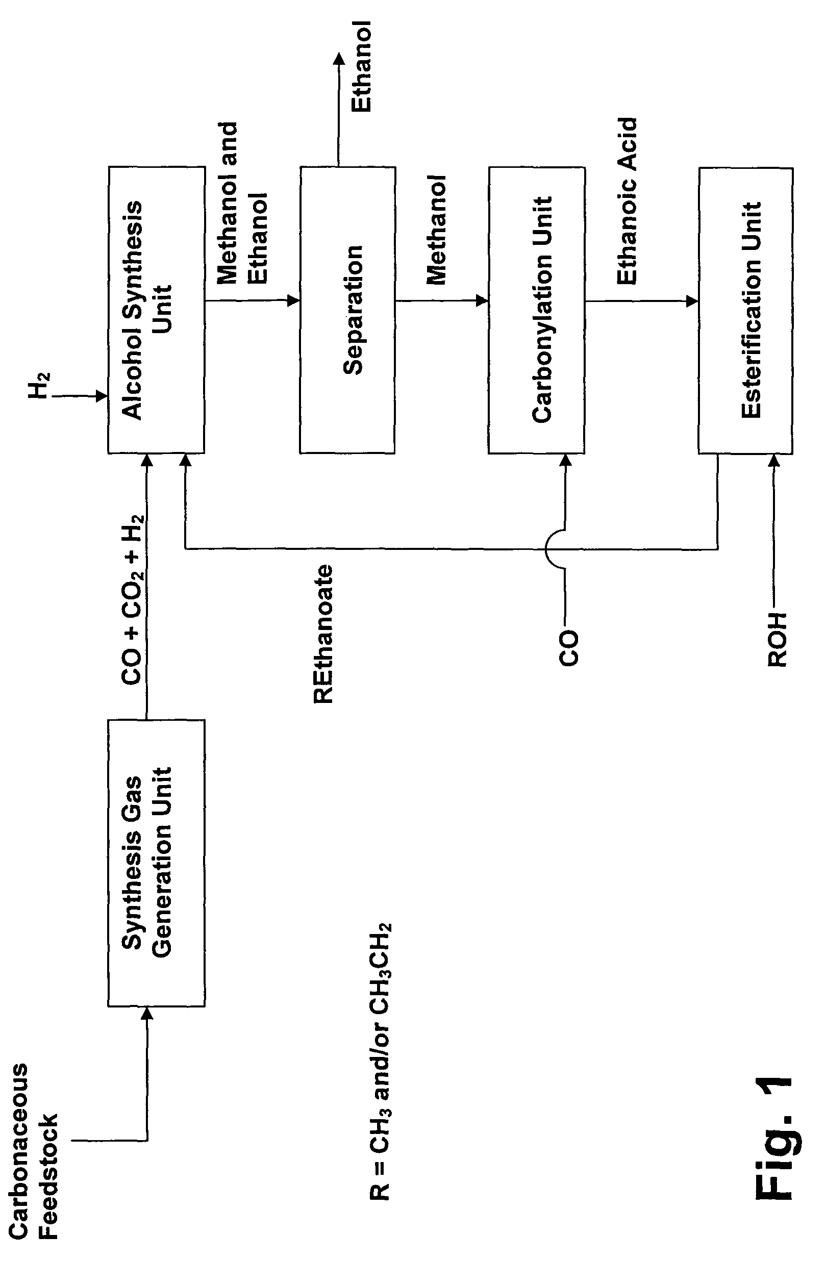
Process for converting synthesis gas to ethanol, including the steps of 1) introducing synthesis gas, together with methyl ethanoate and / or ethyl ethanoate, into an alcohol synthesis unit to produce methanol and ethanol, 2) separating the methanol from the ethanol of step 1, 3) introducing methanol, from step 2, together with CO, into a carbonylation unit in the presence of a methanol carbonylation catalyst, to produce ethanoic acid, and 4) introducing ethanoic acid, from step 3, together with methanol and / or ethanol, into an esterification unit to produce methyl ethanoate and / or ethyl ethanoate. In step 5), methyl ethanoate and / or ethyl ethanoate, produced in step 4, are fed into the alcohol synthesis unit of step 1, and in step 6) ethanol from step 2 is recovered.

Description

[0001]This application is the U.S. national phase of International Application No. PCT / GB2008 / 004095 filed 12 Dec. 2008, which designated the U.S. and claims priority to EP Application No. 07254902.5 filed 17 Dec. 2007, the entire contents of each of which are hereby incorporated by reference.[0002]The present invention relates to a process for the production of ethanol (and optionally methanol) from synthesis gas.[0003]In particular the present invention relates to a process for the production of ethanol from a carbonaceous feedstock; wherein the carbonaceous feedstock is first converted to synthesis gas which is then converted to methanol, which is then converted to ethanoic acid, which is then esterified and which is then hydrogenated to produce ethanol in the same alcohol synthesis unit in which the said synthesis gas is converted to methanol.BACKGROUND OF THE INVENTION[0004]In recent years increased use and demand for alcohols such as methanol, ethanol and higher alcohols has l...

Claims


Application Information

Patent Timeline
IPC IPC(8): C07C27/00C07C67/36C07C51/12C07C27/20
CPCC07C29/149C07C29/154C07C51/12C07C67/08C23F14/02C07C31/08C07C31/04C07C53/08C07C69/14Y02P20/582Y02E50/10
Inventor DANIEL, BERIAN JOHNGRACEY, BENJAMIN PATRICKSUNLEY, JOHN GLENN
Owner INEOS ACETYLS UK LTD
Learn More