
Advanced scroll compressor, vacuum pump, and expander

a scroll compressor and expander technology, applied in the direction of machines/engines, rotary/oscillating piston pump components, liquid fuel engines, etc., can solve the problems of difficult and expensive manufacturing of oil free or oilless scroll compressors and vacuum pumps, limited to a single stage of compression, and links cannot be used in an oil free piece of equipmen

Active Publication Date: 2011-05-17
AIR SQUARED
View PDF21 Cites 31 Cited by
  • Summary
  • Abstract
  • Description
  • Claims
  • Application Information

AI Technical Summary

Benefits of technology

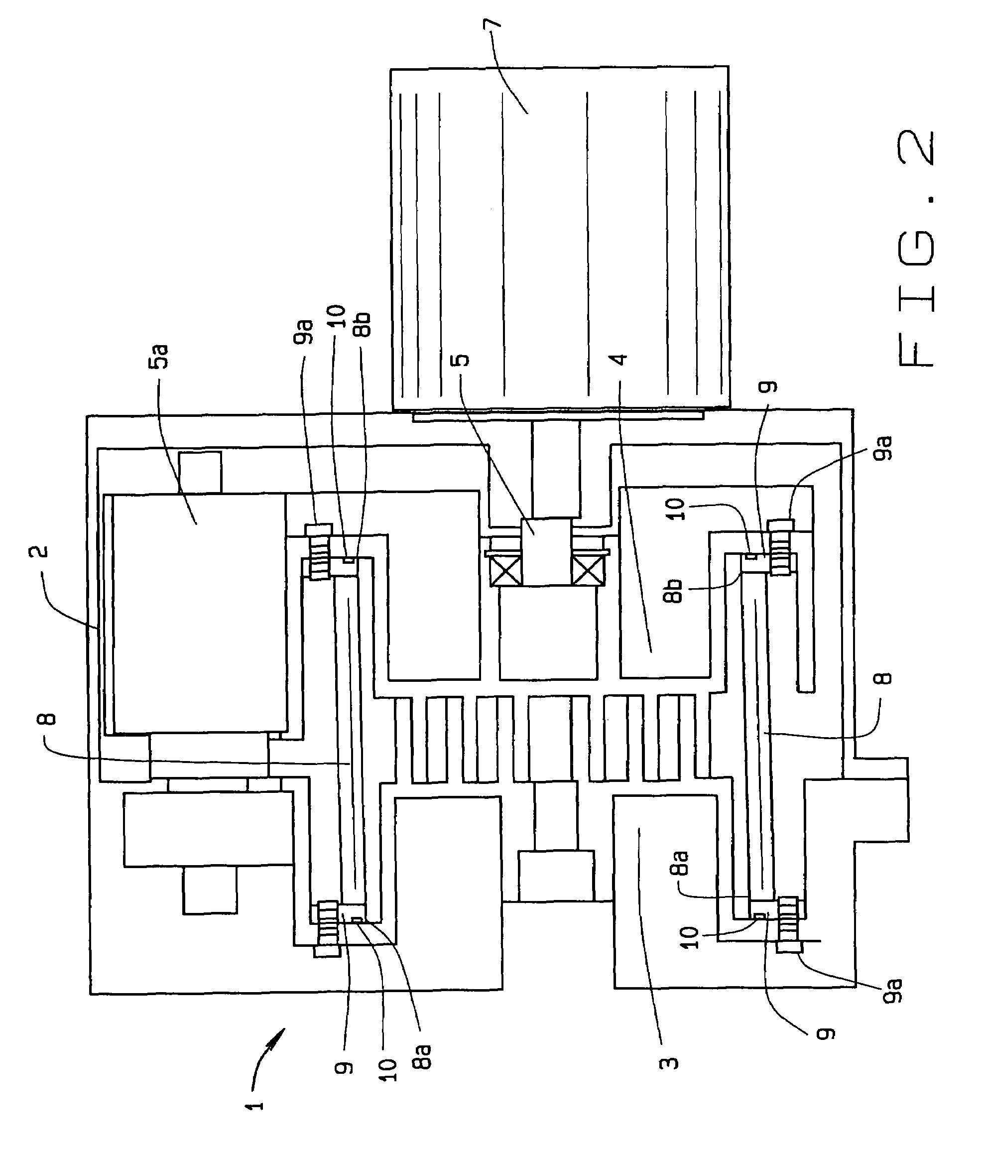
The present invention improves scroll compressors and other equipment with bellows for liquid cooling and a plunger actuated seal for the scroll tips. The invention allows for liquid cooling of a compressor using two bellows, one for inlet and one for outlet. The scrolls have a spiral face with a tight fit to the bellows for evacuating gases. The invention also provides an improved coating on the fixed scroll or involute without using epoxy. The technical effects of the invention include increased efficiency of compressors, hermetic sealing of the scrolls, and a seal that maintains contact with the opposing scroll as the seal wears during use.

Problems solved by technology

In general, they have been limited to a single stage of compression due to the complexity of two or more stages.
Oil free or oilless scroll type compressors and vacuum pumps have difficult and expensive manufacturing, due to the high precision of the scroll in each compressor and pump.
Such links cannot be used in an oil free piece of equipment because of the friction and wear upon the scrolls.
If the fixed and orbiting scrolls in oil free equipment lack precision, leakage will occur and the equipment performance will decline as vacuums take longer to induce or do not arise at all.

Method used


Image

  • Advanced scroll compressor, vacuum pump, and expander
  • Advanced scroll compressor, vacuum pump, and expander
  • Advanced scroll compressor, vacuum pump, and expander

Examples


Embodiment Construction

[0023]The present art overcomes the prior art limitations by modifying scroll compressors and other pumps with bellows, liquid cooling using bellows, and tip seals. Turning to FIG. 1, a scroll compressor 1 appears in a sectional view through the scrolls. The scroll compressor 1 has a case 2 to contain the compressor 1 and scrolls. Within the case 2, the present invention has at least three equally spaced idlers 5a. The idlers rotate eccentrically in cooperation with the scrolls as the scrolls compress or evacuate a gas from a container, not shown. The scrolls are located within the idlers and intermesh. The scrolls have a fixed scroll 3 of a generally spiral shape fixed to the compressor 1 and an orbiting scroll 4 also of a generally spiral shape. The orbiting scroll 4 fits within the fixed scroll 3 and as the orbiting scroll 4 turns, gas is drawn into the scrolls and evacuated from the compressor 1. A bellows 8 surrounds and seals the scrolls while remaining flexible. The bellows 8...


PUM


Abstract

Modifications of a scroll compressor provide a bellows suitable for liquid cooling and a plunger actuated seal for the scroll tips of various equipment. A bellows spans the fixed and the orbiting scrolls and hermetically seals the scroll device. Using two bellows, the present invention allows for liquid cooling of a compressor with an inlet and an outlet to exhaust heated coolant to a heat exchanger. Then the scrolls have a spiral upon a plate that ends in a tip. A seal upon the tip that abuts the fixed scroll upon a biased plunger modifies existing scroll designs to maintain the seal in contact with the fixed scroll. The modifications also provide an improved coating that seals the fixed and orbiting scrolls to each other without the use of epoxy, disassembly, and cleaning.

Description

CROSS REFERENCE TO RELATED APPLICATION[0001]This nonprovisional patent application claims priority to the provisional patent application having Ser. No. 60 / 773,274, which was filed on Feb. 14, 2006. The provisional application was filed during the pendency of PCT application Ser. No. PCT / US01 / 50377 which was filed on Dec. 31, 2001 designating the U.S., and which claimed priority to the U.S. non-provisional application Ser. No. 09 / 751,057 which was filed on Jan. 2, 2001 and is now U.S. Pat. No. 6,511,308.BACKGROUND OF THE INVENTION[0002]The modifications to scroll compressors relate generally to scroll compressors, expanders, and vacuum pumps that alter or reduce the pressure of gases within a container. More specifically, these modifications refer to bellows design, liquid cooling of a compressor, and tip seal improvements.[0003]A unique aspect of the present invention is two bellows that allow liquid cooling of the compressor.[0004]Scroll devices have been used as compressors and v...

Claims


Application Information

Patent Timeline
Patent Type & Authority Patents(United States)
IPC IPC(8): F01C1/02
CPCF04C18/0215F04C29/04F04C2230/91F04C2230/602
Inventor SHAFFER, ROBERT W.
Owner AIR SQUARED
Learn More