
Perimeter

a perimeter and perimetry technology, applied in the field of perimeters, can solve the problems of low credibility on all examination points in the perimetry, difficult for elders or persons with eye disorders to continue to fixate, etc., and achieve the effects of low credibility, short test time, and high credibility

Inactive Publication Date: 2011-05-17
KOWA CO LTD
View PDF10 Cites 7 Cited by
  • Summary
  • Abstract
  • Description
  • Claims
  • Application Information

AI Technical Summary

Benefits of technology

The invention is a perimeter for measuring a visual field by presenting stimuli to an examinee and measuring their fixation state and individual judgment of the stimuli. The perimeter includes a fixation state detecting portion, a criterion outputting portion, a comparison judging portion, and a judged result outputting portion. The invention allows for easier interpretation of the visual field and reduces the burden on both the examiner and the examinee.

Problems solved by technology

Especially, it may be difficult for elderies or persons having eye disorders to continue to fixate a fixation target during a test, and it is necessary to judge as to whether or not an examinee correctly fixates a fixation target in order to execute correct perimetry.
However, a conventional perimeter has such a problem that if an examinee does not correctly fixate a fixation target at a predetermine probability, credibility on all examination points in the perimetry is judged to be low and it is necessary to retry the perimetry thereby.

Method used


Image

  • Perimeter
  • Perimeter
  • Perimeter

Examples


Embodiment Construction

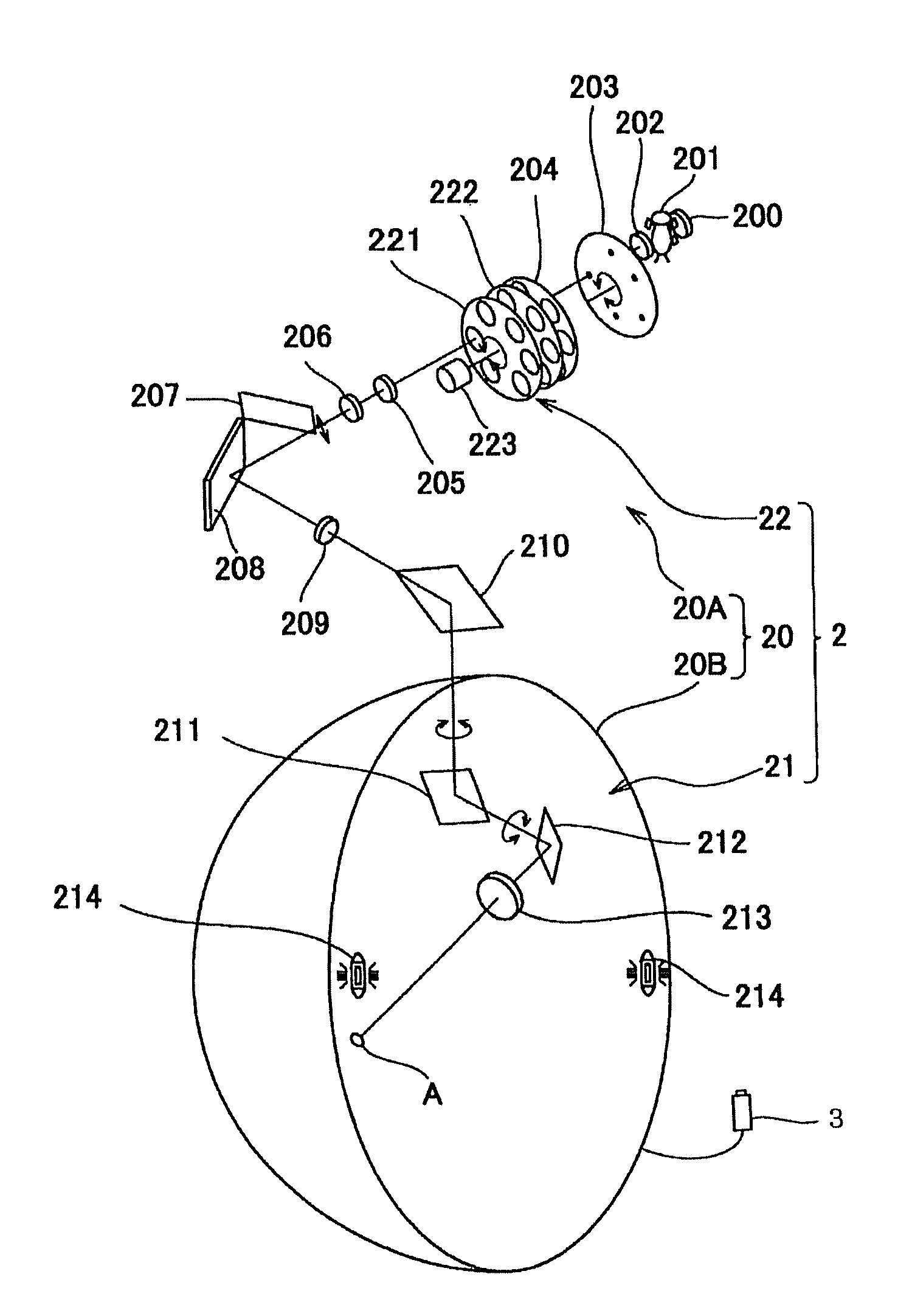
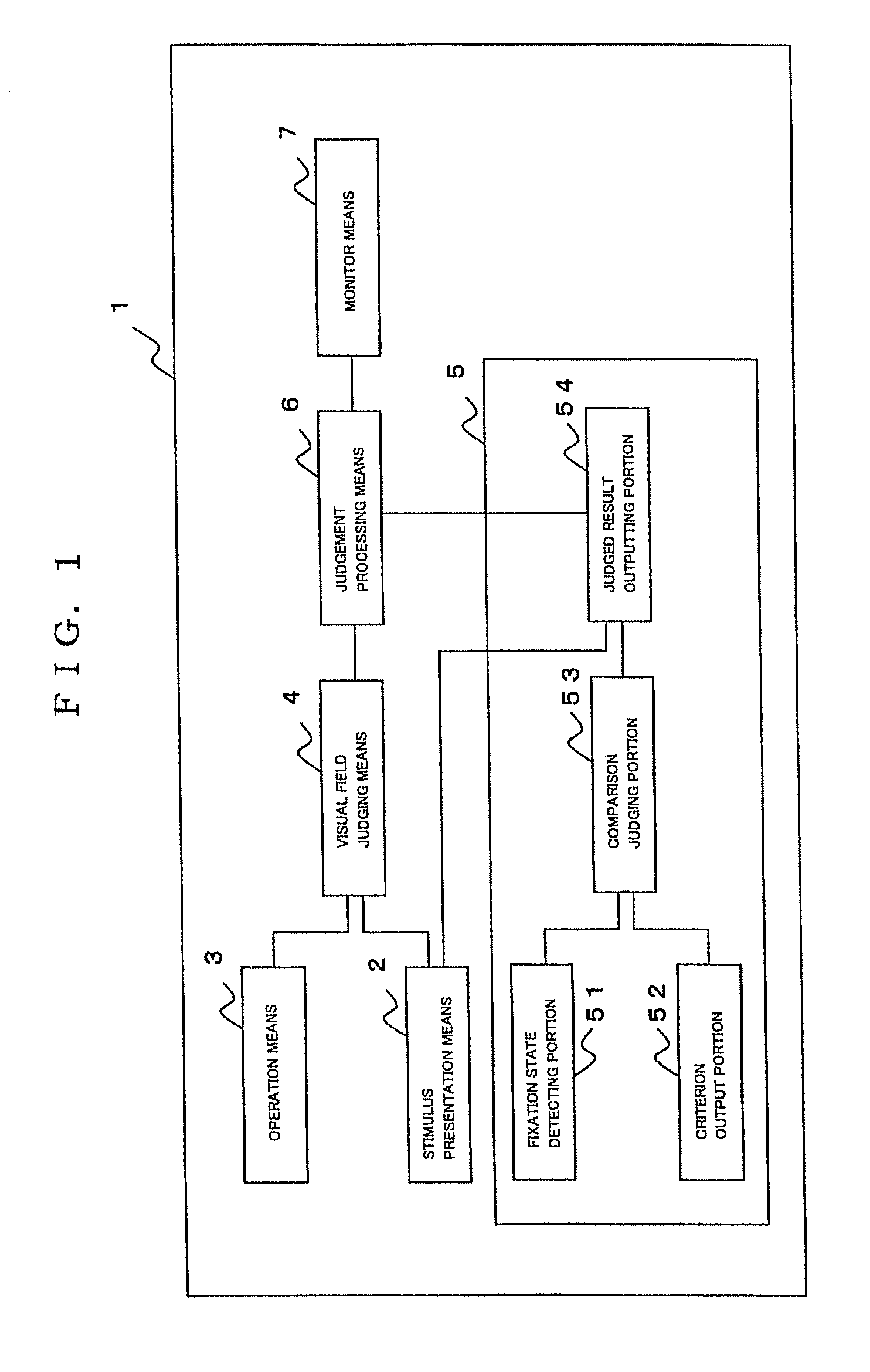
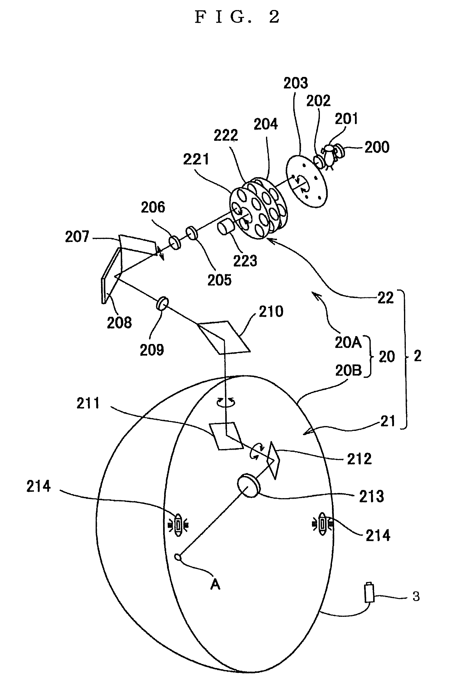
[0031]A best mode for executing the invention is now described, referring to FIGS. 1 to 6. FIG. 1 is a block diagram which shows an example of a structure of a perimeter according to the invention, FIG. 2 is a typical view which shows an example of stimulus presentation means to be used in the perimeter according to the invention, FIG. 3(a) is a typical view for explaining a way of judgment as to whether there is defective fixation or not from a center position of a pupil, FIG. 3(b) is a typical view for explaining a way of judging “defective fixation”, “may be defective fixation” or “no defective fixation” from a center position of a pupil, FIG. 4 is a typical view which shows an example of presentation through monitor means, FIG. 5 is a typical view for explaining calibration of a position of rotation center of an eyeball, and FIG. 6 is a typical view for explaining subjects for fixation state judgment in a threshold perimetry.

[0032]A perimeter according to the invention, which is...


PUM


Abstract

A perimeter has fixation state judging means for individually judging a fixation state of an examinee in connection with each presented stimulus, and the fixation state judging means individually judges the fixation state whenever the stimulus is presented. Even if defective fixation is judged, retest is conducted on only a point where the stimulus was presented, which was judged to be defective fixation. Then, examiner's burden and examinee's burden can be lightened, the test time can be made shorter and test efficiency can be improved in comparison with a case where the whole test is retried from the first as a conventional way.

Description

CROSS REFERENCE TO RELATED APPLICATION[0001]The present disclosure relates to subject matter contained in Japanese patent application No. 2008-259268 filed on Oct. 6, 2008, the disclosure of which is expressly incorporated herein by reference in its entirety.BACKGROUND OF THE INVENTION[0002]This invention relates to a perimeter for measuring a visual field of an examinee in such a state that the examinee fixates a predetermined fixation point.BACKGROUND ART[0003]When suffering from an ophthalmic disease, such as glaucoma and hemianopsia, it is known that a person has a visual field contraction or a visual field defect. For these reasons, perimeters having various structures have been proposed as devices for finding such diseases (see Japanese patent application the publication number of which is 2002-272685).[0004]FIG. 7 is a typical view showing a structure of a conventional perimeter. In FIG. 7, a reference numeral 100 denotes a projection optical system for projecting stimuli A, ...

Claims


Application Information

Patent Timeline
Patent Type & Authority Patents(United States)
IPC IPC(8): A61B3/02
CPCA61B3/0091A61B3/152A61B3/024A61B3/113
Inventor HARA, TAKUYA
Owner KOWA CO LTD
Learn More