
Ring insert for an air intake conduit for an internal combustion engine

Inactive Publication Date: 2011-05-17
MILE EDGE PLUS
View PDF26 Cites 23 Cited by
  • Summary
  • Abstract
  • Description
  • Claims
  • Application Information

AI Technical Summary

Benefits of technology

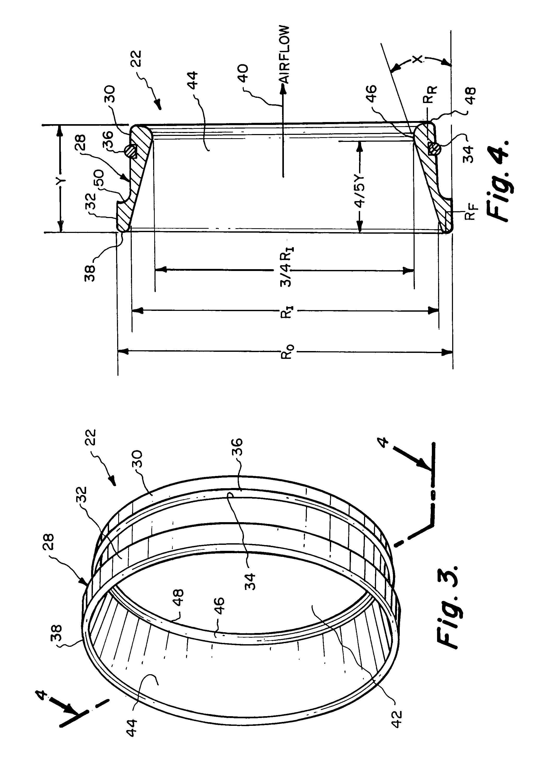
[0008]A first basic embodiment of the present invention is directed to a ring insert for an air intake conduit of an internal combustion engine that utilizes a body which has an outer surface and an inner surface. A portion of the outer surface is to be inserted within an air intake conduit of an internal combustion engine. The body has a forward edge and a rearward edge with both the forward edge and the rearward edge being smoothly contoured. The inner surface of the body includes an annular surface in the shape of a truncated code defining an annular inclined surface that is narrower at the forward edge than at the rearward edge forming a venturi, whereby as air is forced through the body the air is compressed increasing the velocity of the air and decreasing the pressure of the air with the airflow becoming laminar causing increased oxygen to be delivered into the combustion chamber of the engine.

Problems solved by technology

It has been discovered that turbulent air entering in a fuel injection chamber of an internal combustion engine is not the most desirable scenario.
These venturies achieve more complete burning of the fuel, but in the past these venturies have not maximized the fuel burning to achieve maximum efficiency in the combustion of the fuel within the engine.
Additionally, these venturies required substantial modification of the air throttle passage or inlet conduit and therefore unless such venturies are incorporated at the time of manufacturing the internal combustion engine, widespread usage of such venturies in conjunction with air inlet conduits has not been achieved.

Method used


Image

  • Ring insert for an air intake conduit for an internal combustion engine
  • Ring insert for an air intake conduit for an internal combustion engine
  • Ring insert for an air intake conduit for an internal combustion engine

Examples


Embodiment Construction

[0027]Referring particularly to the drawings, there is shown in FIG. 1 an air intake hose 10 of an air throttle system of an internal combustion engine. Generally, the hose 10 will be constructed of a rubber or plastic composition. The air throttle system includes an air intake conduit 12 which will be constructed of a metallic material, usually aluminum or steel. The air intake conduit 12 includes a connection area 14 located directly adjacent the entrance into the conduit 12. The connection area 14 is terminated at its inner end by an annular shoulder 16. A clamping band 18, which can be tightened and loosened by turning of screw 20, is mounted about the hose 10 and functions to tightly clamp the hose 10 onto the connection area 14 of the air intake conduit 12 with the hose 10 abutting against shoulder 16. The ring insert 22 of this invention is designed to be located within both the internal passage 24 of the air intake conduit 12 and also within the internal passage 26 of the ai...


PUM


Abstract

A ring insert for an air intake conduit for an internal combustion engine comprising a sleeve-shaped body which is tightly mounted within the air intake conduit. The body has an inner surface which includes an annular surface in the shape of a truncated cone defining an annular inclined surface that is narrower at the forward edge of the body than at the rearward edge forming a venturi directly adjacent the rearward edge. The forward edge of the body is smoothly contoured and the rearward edge of the body is smoothly contoured.

Description

BACKGROUND OF THE INVENTION[0001]1. Field of the Invention[0002]The present invention relates generally to inserts for intake conduits for an internal combustion engine for the purpose of increasing oxygen flow into the combustion chambers of the engine to increase power thereby achieving greater torque and horsepower, increase gas mileage and have the engine run leaner to decrease smog and burn less fuel.[0003]2. Description of the Related Art[0004]Every internal combustion engine intakes air with the oxygen in the air being used to achieve burning of the fuel within the combustion chambers of the engine. If there is supplied more than an adequate amount of air, there is supplied a more than adequate amount of oxygen to achieve the leanest possible combustion of the fuel within the combustion chambers. The more oxygen that is supplied within the combustion chambers the more complete ignition of the fuel is achieved within the combustion chamber. The more complete the burning of the...

Claims


Application Information

Patent Timeline
IPC IPC(8): F02M29/00G01F1/42
CPCF02M35/10118
Inventor ROCKWELL, KIRK J.
Owner MILE EDGE PLUS
Learn More