
Digital video interface with bi-directional half-duplex clock channel used as auxiliary data channel

a digital video interface and clock channel technology, applied in the field of digital video interfaces, can solve the problems of inefficient use of clock channels in conventional digital video interfaces, and achieve the effect of efficiently using channels, sacrificing data channel performance, and changing channel composition

Active Publication Date: 2011-05-10
SILICON IMAGE INC
View PDF7 Cites 11 Cited by
  • Summary
  • Abstract
  • Description
  • Claims
  • Application Information

AI Technical Summary

Benefits of technology

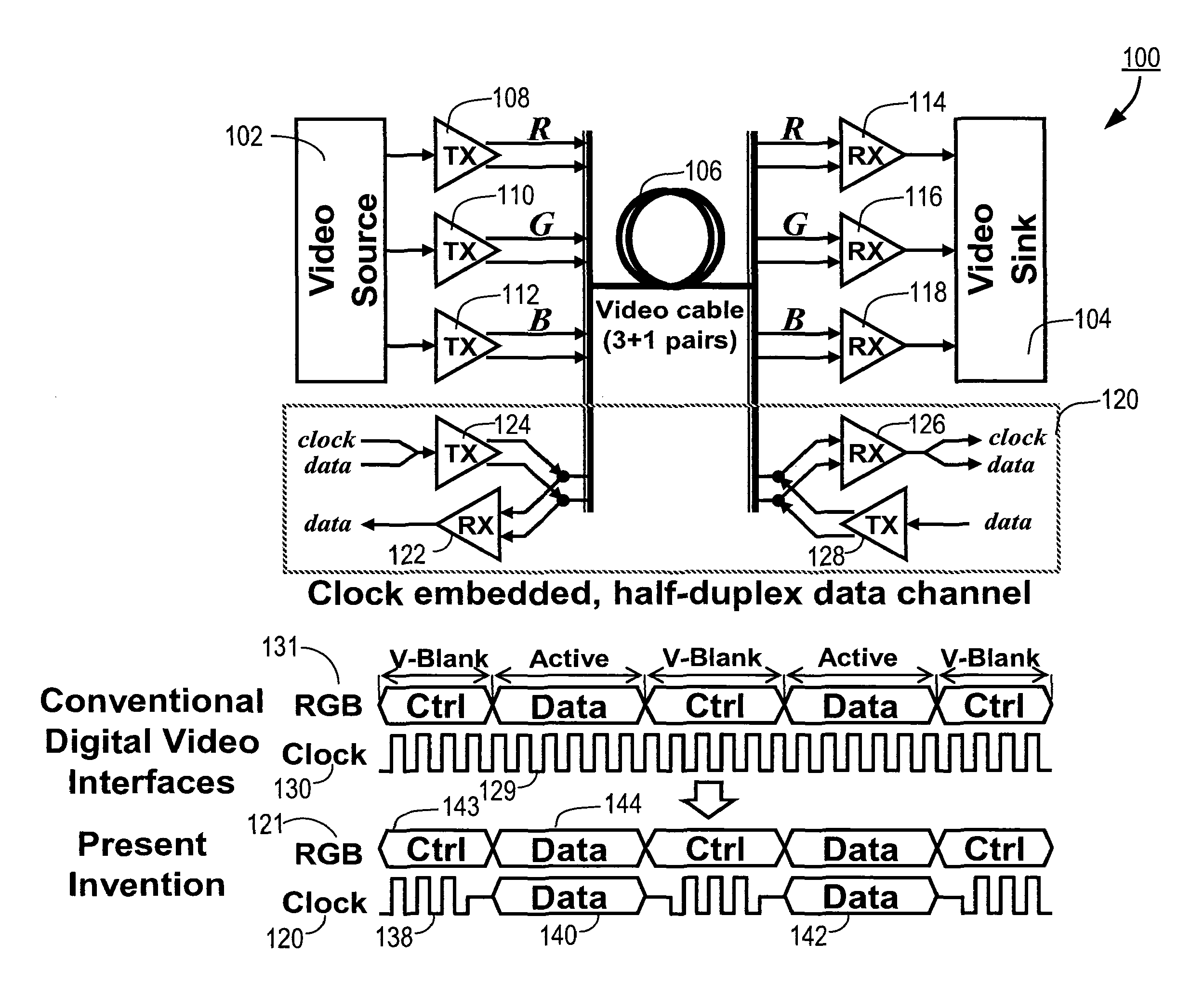
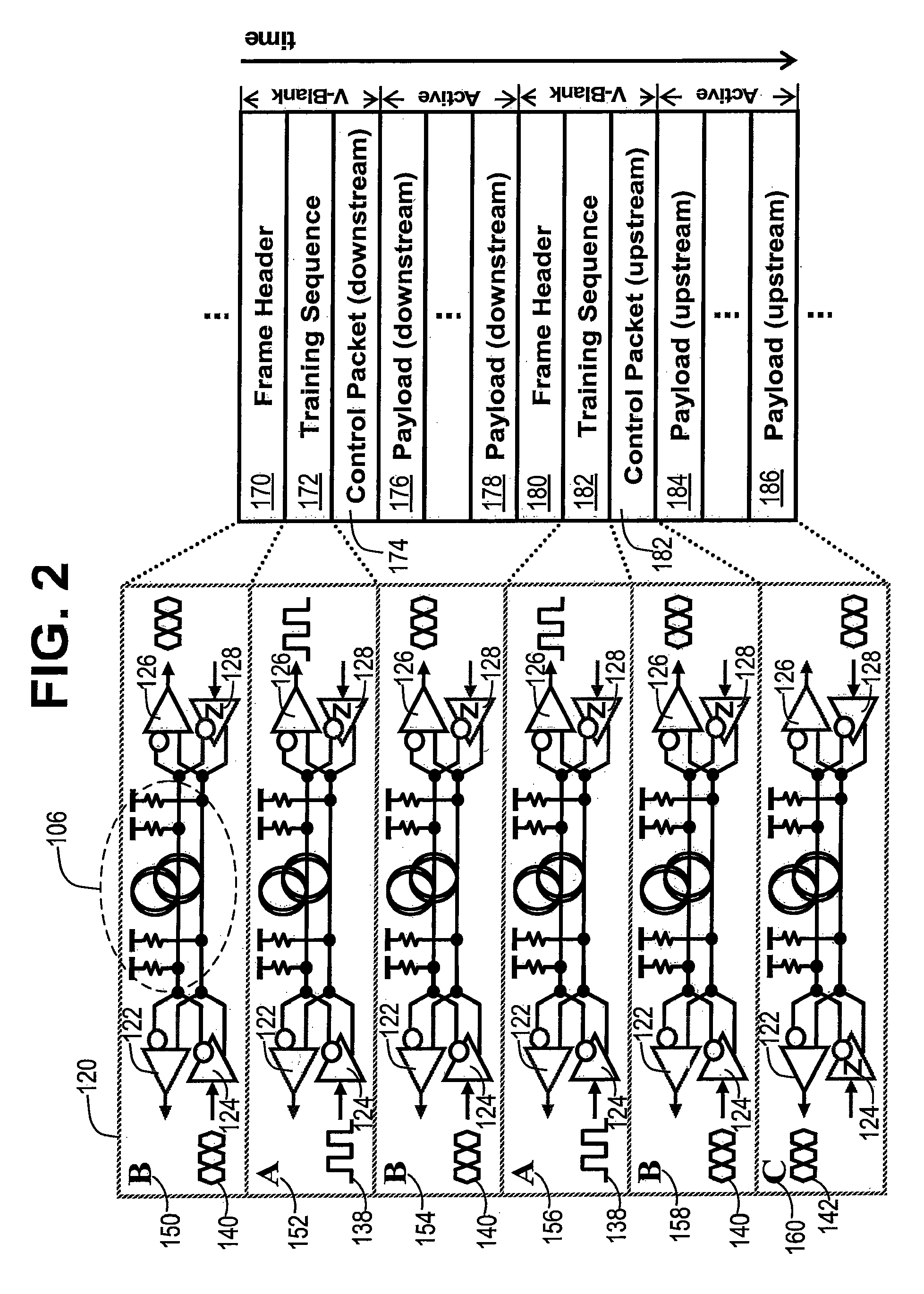
"The present invention is a digital video interface system and method that uses the clock channel for transmitting data and clock signals in a bi-directional, half-duplex manner. The system includes data channels and a clock channel that operate in time division multiplexing with first and second time slots. The clock channel can transmit additional data in the opposite direction from the sink device to the source device in the second time slots. The system allows for efficient use of the clock channel and increased data communication without changing the channel composition of the digital video interfaces. The technical effects of the invention include improved data transmission and utilization of the clock channel."

Problems solved by technology

Thus, conventional digital video interfaces use the clock channel inefficiently, transmitting the clock signal continuously even when the frequency information may not be needed at the video sink.
This results in inefficient use of the clock channel.

Method used


Image

  • Digital video interface with bi-directional half-duplex clock channel used as auxiliary data channel
  • Digital video interface with bi-directional half-duplex clock channel used as auxiliary data channel
  • Digital video interface with bi-directional half-duplex clock channel used as auxiliary data channel

Examples


Embodiment Construction

[0021]The Figures (FIG.) and the following description relate to preferred embodiments of the present invention by way of illustration only. It should be noted that from the following discussion, alternative embodiments of the structures and methods disclosed herein will be readily recognized as viable alternatives that may be employed without departing from the principles of the claimed invention.

[0022]Reference will now be made in detail to several embodiments of the present invention(s), examples of which are illustrated in the accompanying figures. It is noted that wherever practicable similar or like reference numbers may be used in the figures and may indicate similar or like functionality. The figures depict embodiments of the present invention for purposes of illustration only. One skilled in the art will readily recognize from the following description that alternative embodiments of the structures and methods illustrated herein may be employed without departing from the pr...


PUM


Abstract

A digital video interface system and method for communicating digital video data from a source device to a sink device is provided, where the clock channel is used to transmit data as well as clock signals in a bi-directional, half-duplex manner using time division multiplexing. The digital video interface system comprises one or more data channels configured to transmit digital video data from the source device to the sink device in time divisional multiplexing including a plurality of first time slots and second time slots, and a clock channel configured to transmit a clock signal from the source device to the sink device in the first time slots and configured to transmit additional data from the source device to the sink device or from the sink device to the source device in the second time slots.

Description

CROSS-REFERENCE TO RELATED APPLICATION[0001]This application claims priority under 35 U.S.C. §119(e) from co-pending U.S. Provisional Patent Application No. 60 / 910,759, entitled “Digital Video Interface with Bi-Directional Half-Duplex Auxiliary Data Channel,” filed on Apr. 9, 2007, which is incorporated by reference herein in its entirety.BACKGROUND OF THE INVENTION[0002]1. Field of the Invention[0003]The present invention relates to a digital video interface and, more specifically, to a digital video interface that uses the clock channel as an auxiliary data channel.[0004]2. Description of the Related Art[0005]Current digital video interfaces such as DVI (Digital Video Interface), HDMI (High-Definition Multimedia Interface), and UDI (Unified Display Interface) typically use 3 or 6 RGB (Red, Green, and Blue video data) channels for the main data stream and 1 clock channel for a frequency reference, in order to transmit digital video data between a video source device (e.g., a digita...

Claims


Application Information

Patent Timeline
Patent Type & Authority Patents(United States)
IPC IPC(8): H04J3/12H04N21/436
CPCH04N11/042H04L5/16H04L7/0008H04N9/64H04N7/10H04N9/44H04N5/775H04N5/44
Inventor LEE, BONG-JOON
Owner SILICON IMAGE INC
Learn More