Method of thermally insulating coaxial pipes with a particulate insulating material

Inactive Publication Date: 2011-05-10
SAIPEM SA
View PDF10 Cites 52 Cited by
  • Summary
  • Abstract
  • Description
  • Claims
  • Application Information

AI Technical Summary

Benefits of technology

[0033]The oblique position of the string allows the particles of insulating material to travel naturally along the annular space under the effect of gravity until they reach the rising front of insulating material. Below the rising front, the annular space is normally completely filled with insulating material, whereas above the rising front, the annular space is completely empty thus facilitating downward progress of particles under the effect of gravity.
[0085]For particles that are accurately spherical and of constant diameter, the theoretical filling coefficient varies depending on the way in which the spheres stack, between a minimum value of 0.52376 (π / 6) to a maximum value of 0.7405 (π / 3√2). The mere fact of shaking all of the particles while filling is taking place serves to approach said maximum filling coefficient. Said filling coefficient is advantageously improved by using an insulating material made up of granules having staged diameters, in particular in the range 10 μm to 5 mm so that the small granules are received in the gaps between granules of larger diameter, then making it possible to achieve filling coefficients in the annular that are greater than 0.85, and in particular that lie in the range 0.85 to 0.95.

Problems solved by technology

Thus, the problem posed is to provide PiP type coaxial pipes presenting thermal insulation in their annular space, which insulation is both effective in terms of the insulation it provides and is also simple to make and to put into place in the annular space between said pipe.

Method used


Image

  • Method of thermally insulating coaxial pipes with a particulate insulating material
  • Method of thermally insulating coaxial pipes with a particulate insulating material
  • Method of thermally insulating coaxial pipes with a particulate insulating material

Examples


Embodiment Construction

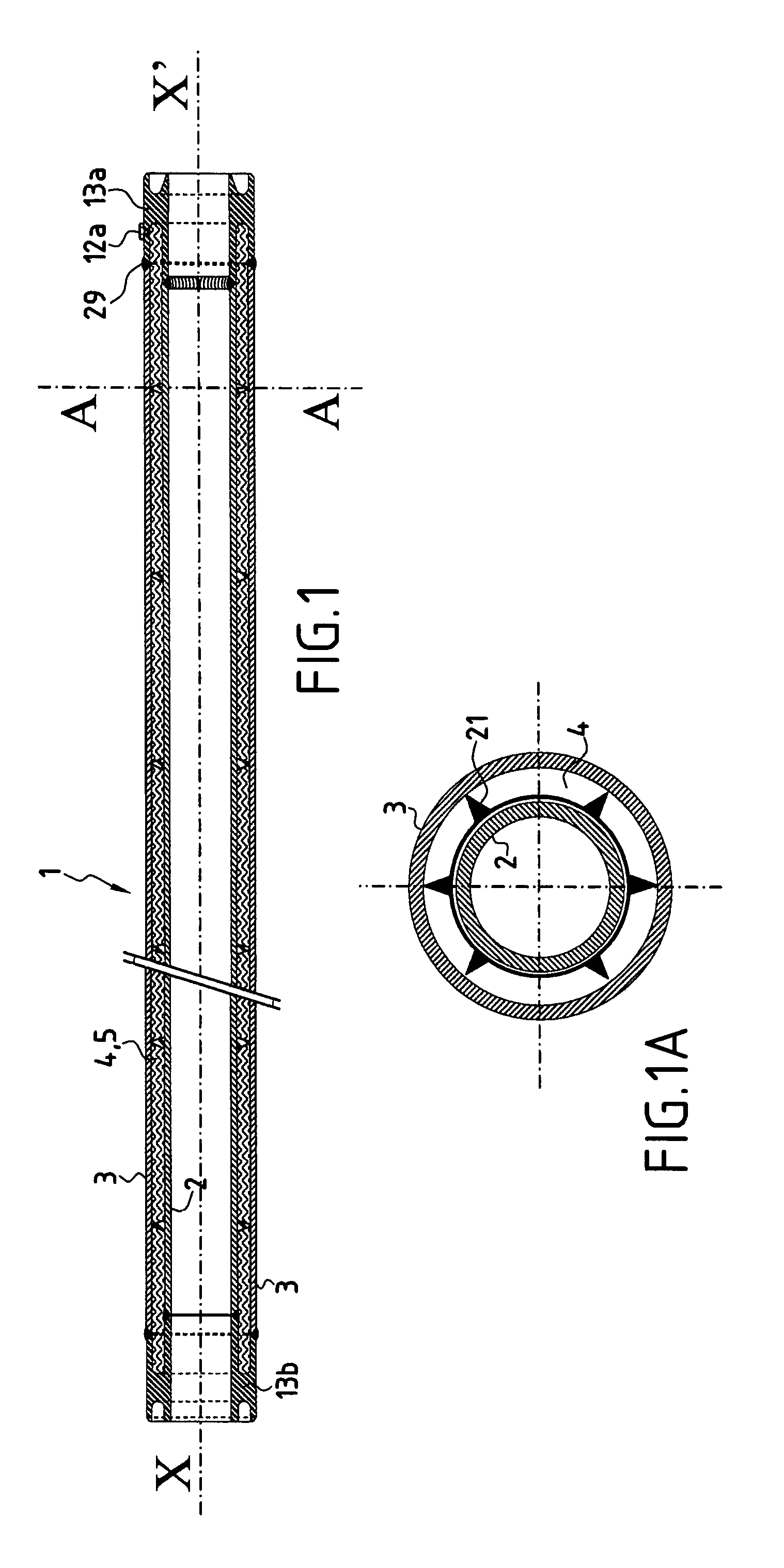
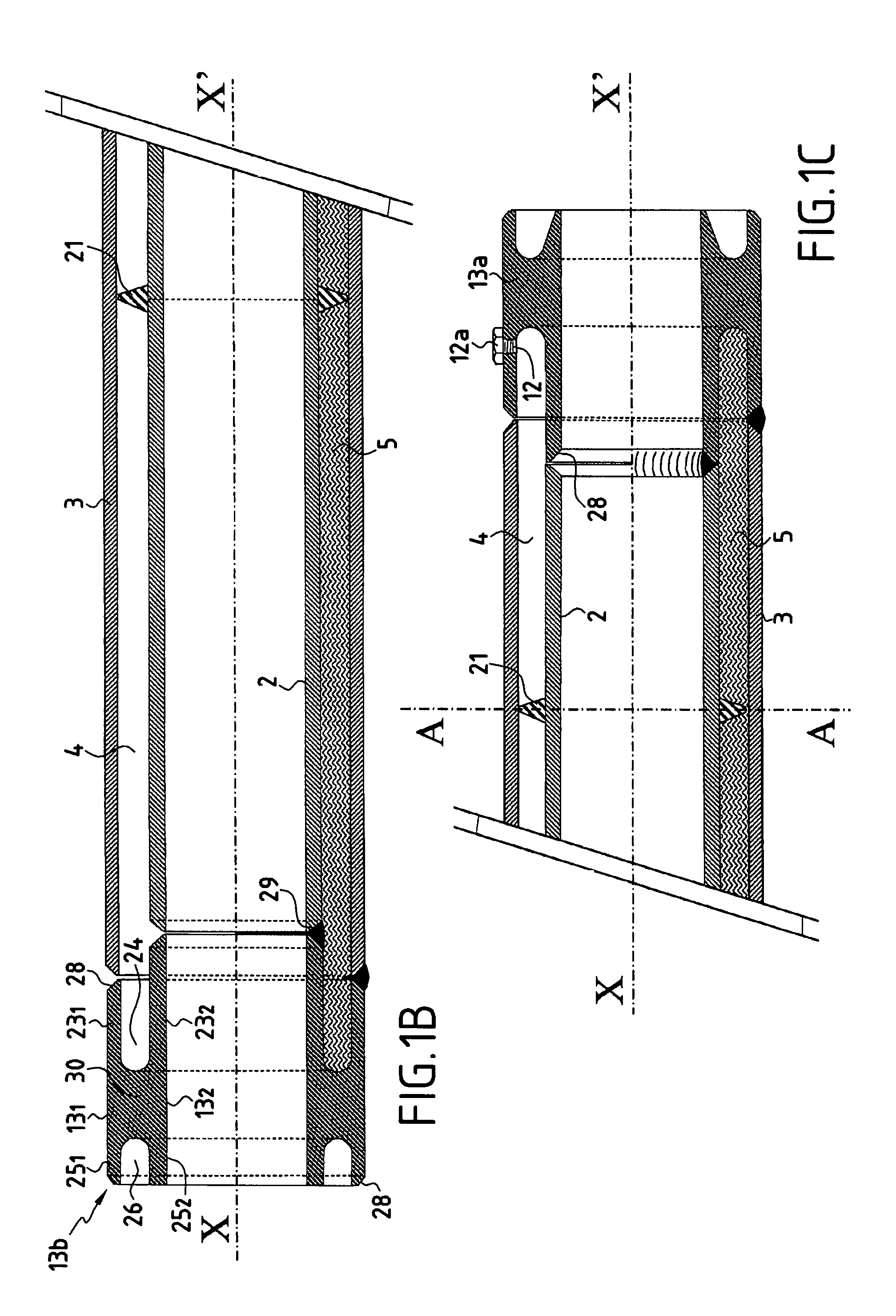
[0100]In FIGS. 1, 1B, and 1C, there can be seen a PiP type pipe 1 constituted by an outer pipe 3 and an inner pipe 2 secured by welding to a first junction forging 13b situated to the left in FIG. 1B and to a second junction forging 13a situated to the right in FIG. 1C, the annular space between said inner and outer pipes being filled with a micro- or nanoporous insulating material 4, with centralizer elements 21 around the circumference of the inner pipe and spaced apart, preferably in regular manner, along the length thereof. These centralizers maintain the radial distance between the inner and outer pipes and thus they maintain the thickness of said annular space at a value that is substantially constant.

[0101]Said junction forgings 13a and 13b are defined as follows:[0102]in a radial direction relative to a longitudinal axis XX′ of symmetry of said forging, said forgings are defined by a cylindrical inside wall 132 having substantially the same diameter as the main portion of sa...


PUM

PropertyMeasurementUnit
Lengthaaaaaaaaaa
Lengthaaaaaaaaaa
Fractionaaaaaaaaaa

Abstract

A method of thermally insulating the annular space in an element of an assembly of two coaxial pipes, the space being filled with a porous thermally insulating material, under low absolute gas pressure in which method the following steps are performed: a) the pipe element is inclined, preferably at an angle α of 5° to 30°, the annular space being closed at each end by respective closure pieces; and b) substantially all of the annular space is filled with the insulating material in the form of particles in bulk; and c) preferably said particles of insulating material are shaken, at least intermittently, as the annular space is filled in order to compact the insulating material, the annular space being maintained under high vacuum during filling.

Description

PRIORITY CLAIM[0001]This is a U.S. national stage of application No. PCT / FR2005 / 003062, filed on Dec. 7, 2005. Priority is claimed on the following application: Country: France, Application No.: 04 / 13050, Filed: Dec. 8, 2004 the content of which is incorporated here by reference.FIELD OF THE INVENTION[0002]The present invention relates to a method of thermally insulating a coaxial pipe assembly, in particular for undersea pipes for conveying hot or cold fluids, and preferably undersea pipes for use in great depths.[0003]More particularly, the invention relates to a method of thermally insulating the annular space between two coaxial pipes comprising an inner pipe and an outer pipe.[0004]The present invention relates in particular to insulating such undersea pipes installed in oil fields at very great depths, and also to bottom-to-surface connection pipes suspended between the bottom of the sea and a surface ship anchored over said oil field.[0005]Such coaxial pipe assemblies are mad...

Claims


Application Information

Patent Timeline
IPC IPC(8): B65B31/04F16L9/14
CPCF16L59/028F16L59/143F16L59/065
Inventor CARLIER, BORISLANDREAU, BENOIT
Owner SAIPEM SA
Why Eureka
Try Eureka