
Automatic test equipment self test

a self-testing, test equipment technology, applied in the direction of automated test systems, air break switches, instruments, etc., can solve the problems of increasing the cost of automatic test station design, increasing the cost of self-test adaptors to accommodate instrument resource changes, and increasing the cost of engineering resources, so as to prolong the schedule, increase costs, and increase costs

Inactive Publication Date: 2011-05-03
HONEYWELL INT INC
View PDF10 Cites 4 Cited by
  • Summary
  • Abstract
  • Description
  • Claims
  • Application Information

AI Technical Summary

Benefits of technology

The patent text describes a self test adapter (STA) for automatic test equipment (ATE) that can be used to verify the function of the ATE station resources before testing the product. The STA is designed to be modular, scalable, and configurable, with the ability to easily modify and adapt to different ATE station resources. This reduces the cost and risk of faulty test results, and also avoids the need for dedicated self test adapters that may result in inconsistent test results and increased engineering resources. The technical effects of the patent text include improved efficiency and accuracy in testing ATE stations, reduced costs, and improved scalability and adaptability.

Problems solved by technology

This dependency on station resources can increase the cost of automatic test station design due to the dedicated resources for a self test adapter which may not be needed otherwise.
Manufacturing of custom build self test adapters by individual technicians can cause fabrication variances between identical self test adapter designs.
Variances include inconsistency of wire lengths, wire crimping to connectors, contact soldering, and wire routing that causes inconsistent path resistance resulting in fluctuating test results from identical self test adapter designs.
Modifications or additions to the self test adaptors to accommodate instrument resource changes increase cost by consuming engineering resources, injecting unforeseen errors and extending the schedule.
The actual modification of the STA may compromise the electrical integrity such as wire breaks caused by moving wires back and forth.
As a result, these modifications may increase costs, delays, and cause inaccuracies in obtained test data.
In some cases, the engineering design, manufacturing, and cost of acquiring today's complex and specific STA designs may influence a decision to not implement the STA, further increasing risk.

Method used


Image

  • Automatic test equipment self test
  • Automatic test equipment self test
  • Automatic test equipment self test

Examples


Embodiment Construction

[0024]The following detailed description of the invention is merely exemplary in nature and is not intended to limit the invention or the application and uses of the invention. Furthermore, there is no intention to be bound by any theory presented in the preceding background of the invention or the following detailed description of the invention.

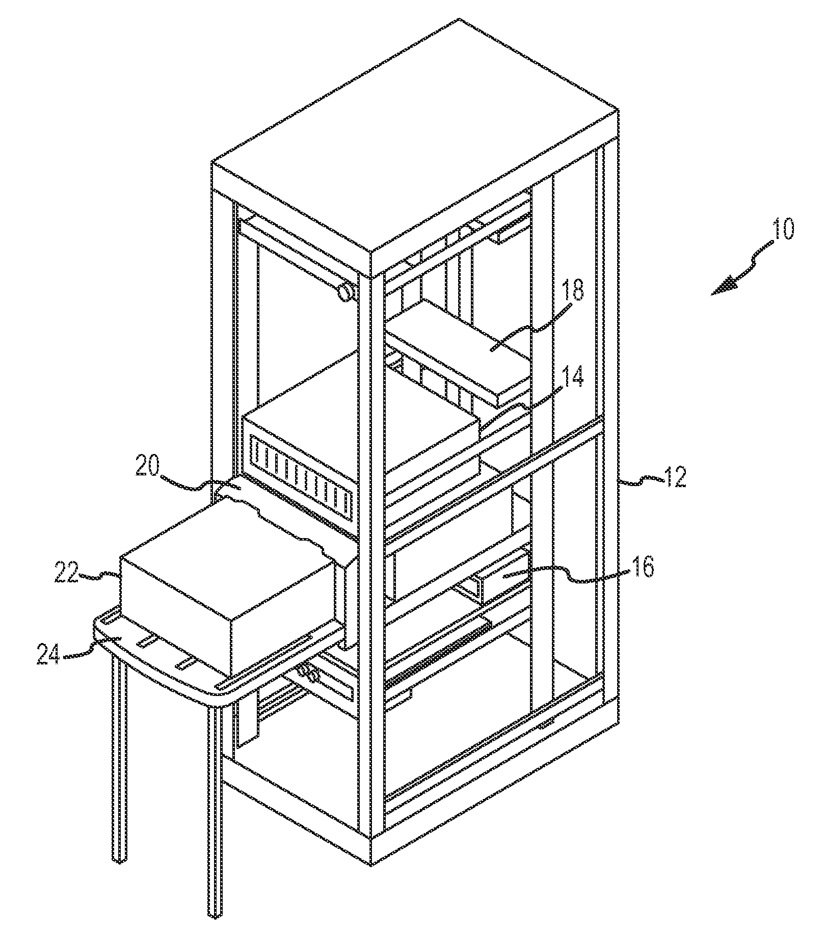
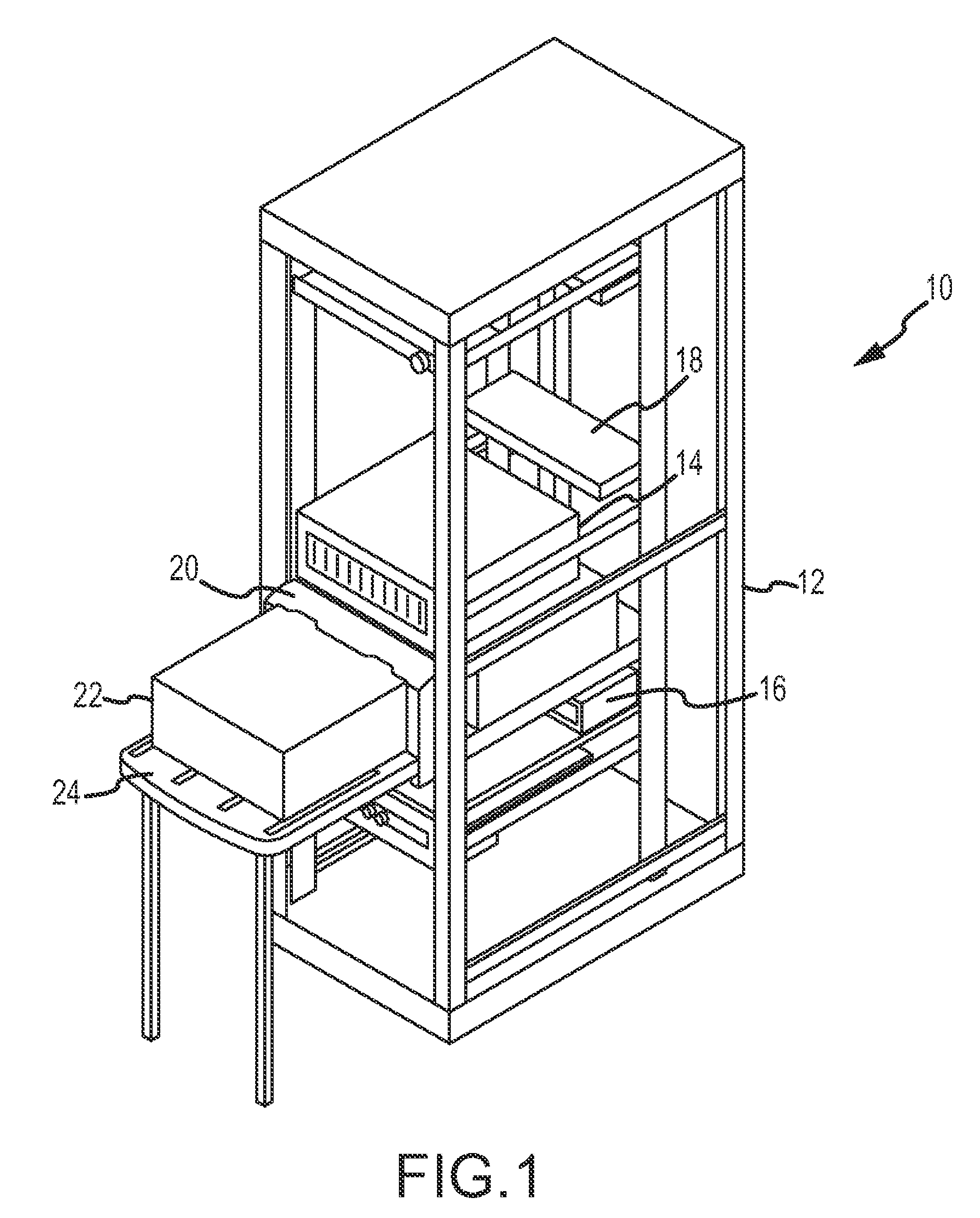
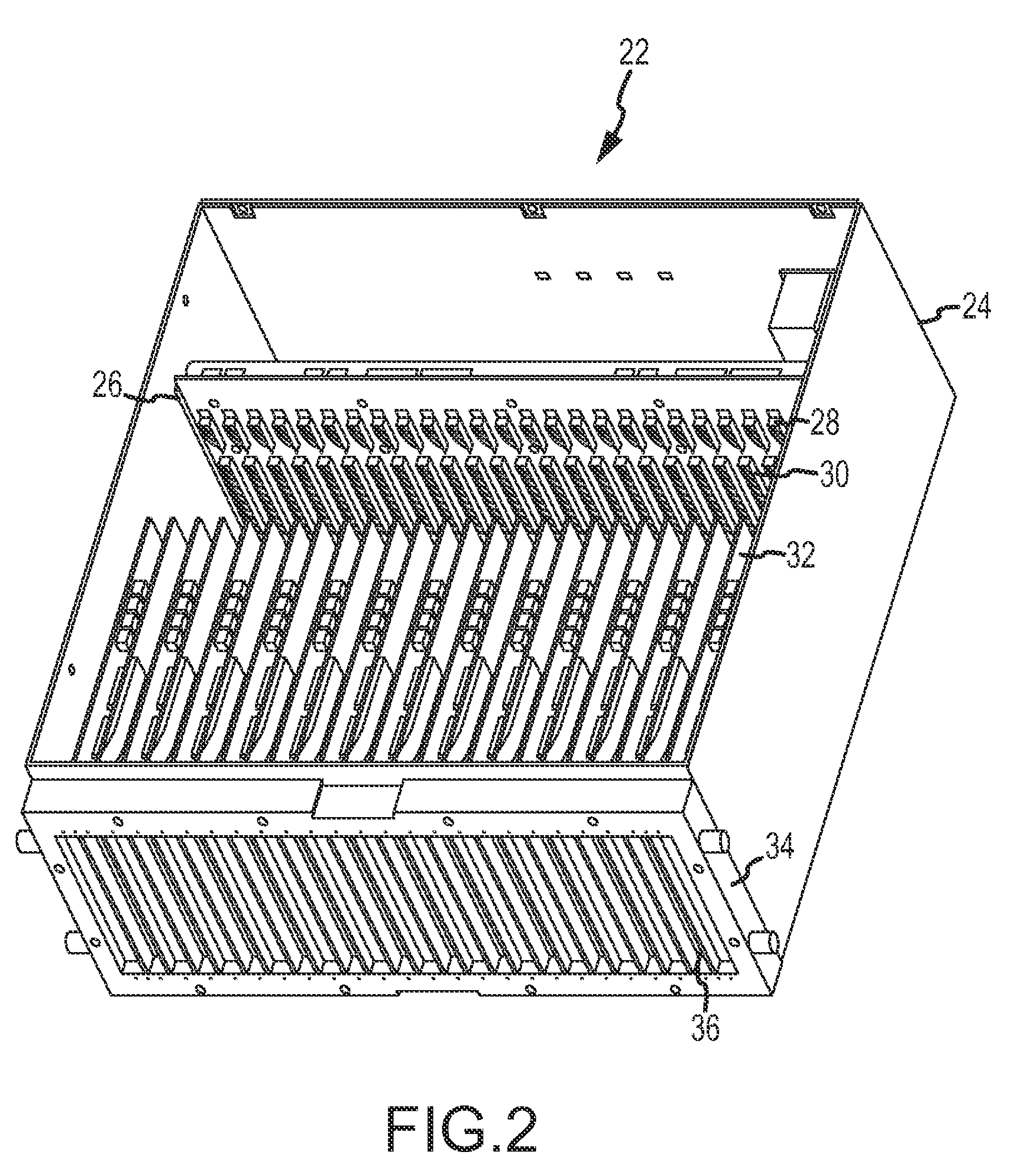
[0025]The following description and claimed subject matter present illustrated embodiments of a generic, modular, and scalable self test adapter (STA) for automatic test equipment (ATE) station resources. The illustrate embodiments independently validate commercial ATE station resources, yet are configurable for a user to easily modify for differing ATE station configurations (differing resource combinations or number of resources).

[0026]The modular design approach seen in the illustrated embodiments reduces engineering effort, uses standard control software architecture, and provides a common method for testing station resources independent...


PUM


Abstract

A self test adapter (STA) for automatic test equipment (ATE) is provided. The STA includes an enclosure. A backplane is housed by the enclosure. A dual data bus is integrated into the backplane. At least one STA card module is inserted into the backplane. The at least one STA card module has a port for interconnection with an ATE station receiver. The at least one STA card module includes a generic region adapted for interfacing with an additional STA card module over the dual data bus, and a resource specific region adapted for self test of at least one ATE station resource.

Description

FIELD OF THE INVENTION[0001]The present invention generally relates to test equipment for electronics systems, and more particularly, but not exclusively, to a self test adapter (STA) for automatic test equipment.BACKGROUND OF THE INVENTION[0002]Automatic test equipment (ATE) refers to automated devices used to perform testing on electronic systems and devices, such as systems incorporated into automotive, aerospace, marine and other environments. In many industries, such as the aircraft industry, ATE performs valuable diagnostic functionality, such as diagnosis and prognosis of aircraft systems and devices.[0003]ATE devices may be used to quickly and efficiently test electronics devices such as printed circuit boards (PCBs), integrated circuits (ICs), and other related electronic components or modules. ATE devices may be controlled by computers or computing environments, proprietary controllers, or even relay controls.[0004]An ATE system, or resource, may be a simple as a digital m...

Claims


Application Information

Patent Timeline
Patent Type & Authority Patents(United States)
IPC IPC(8): G01R31/02
CPCG01R31/31901G01R31/2834G01R35/00G01R31/31907
Inventor NORDSTROM, KENNYJONES, RALPHMUNIRATHNAM, KRISHNA
Owner HONEYWELL INT INC
Learn More