
Liquid dispenser

a dispenser and liquid technology, applied in the field of liquid dispensers, can solve the problems of inability to output liquid in any direction, complex structure, and inability to meet the needs of liquid transferring devices, etc., and achieve the effect of good effect and new design

Active Publication Date: 2011-04-26
YUAN JIANJUN
View PDF11 Cites 20 Cited by
  • Summary
  • Abstract
  • Description
  • Claims
  • Application Information

AI Technical Summary

Benefits of technology

[0003]The technical problem to be solved by the disclosure herein is to provide an improved liquid dispenser over the aforesaid state of the art, and which is novel in design, simple and compact in construction, while providing a good effect when in use. Furthermore, it can be used in any direction without affecting normal function.
[0012]Besides the two different technical solutions as mentioned above, further modifications can be made on the basis of the two solutions, for instance, extending a circular tube upward and downward on the valve plate I according to the aforesaid structural basis, wherein the upper circular tube is inserted into the chamber of the main body and the two are sealingly engaged. The lower circular tube covers an inner circular tube of the cover and the two are sealingly engaged. This allows the liquid to pass through orifices outside the inner circular tube of the cover, avoiding the spring and the valve from being in contact with the liquid.
[0014]In comparison with the state of art, the advantages of the present invention are as follows:1. Since the liquid dispenser described employs the operation principle of one-way valve, this liquid dispenser can make liquid discharge in any direction without affecting the usage;2. Instead of having any head cap of such conventional liquid dispensers, the liquid dispenser herein realizes the liquid dispensing function of liquid by pressing a button. Therefore, the liquid dispenser can minimize the use of space;3. The dispenser herein is compact in construction with less parts;
[0015]4. At the same time, this liquid dispenser can function as a vacuum liquid dispenser, by making the mated piston type container, having for example a double-layer thin film flexible container, reduce in volume as the liquid inside reduces. Such as configuration can avoid any air contact with unused liquid during storage.

Problems solved by technology

However, at present the publicly-known liquid dispenser requires more parts to be built.
The structure is complicated while not compact in construction.
Furthermore, after the dispenser is assembled with the container, it cannot be used to output liquid in any direction because of its internal structure.

Method used


Image

  • Liquid dispenser
  • Liquid dispenser
  • Liquid dispenser

Examples


embodiment 1

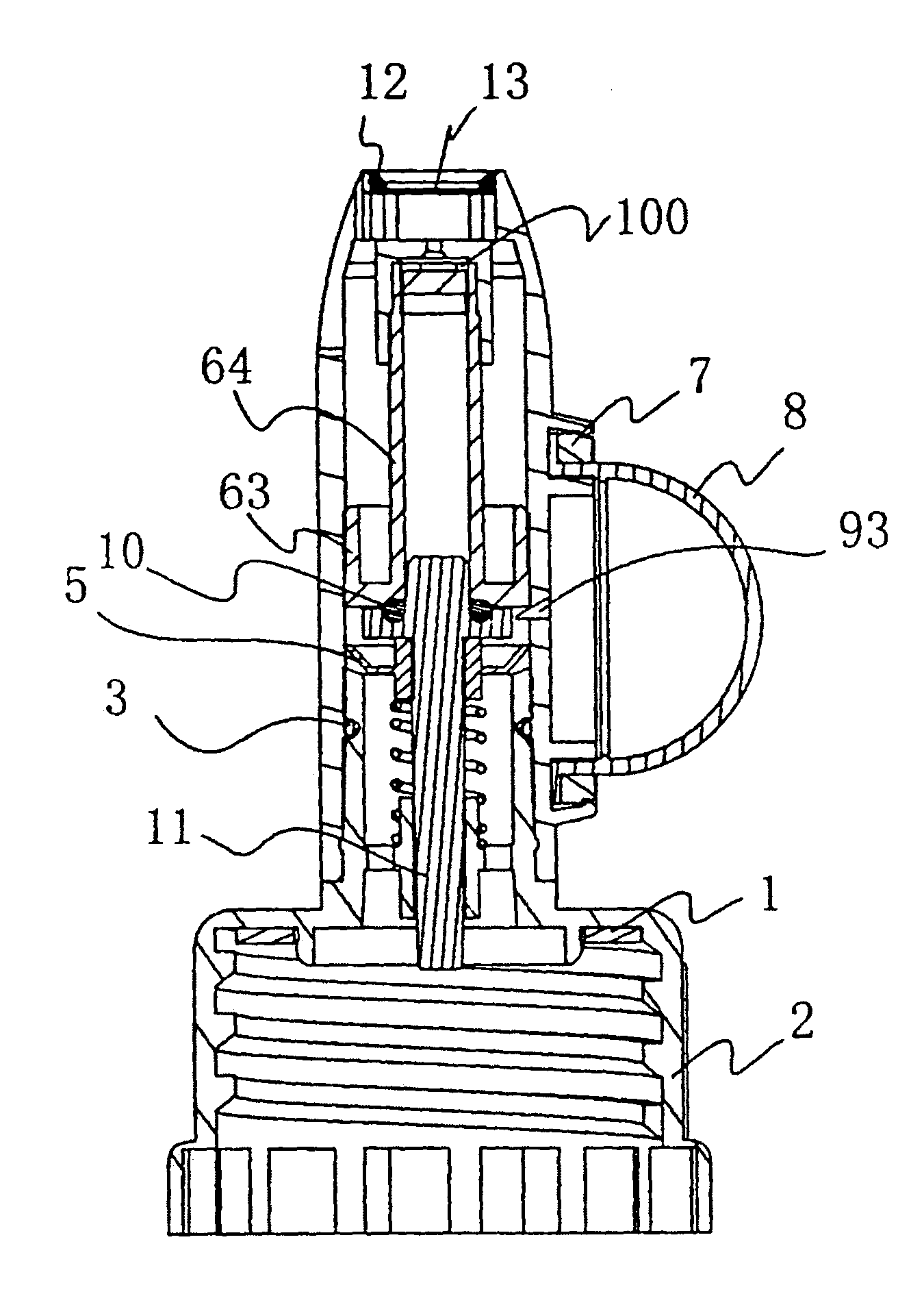
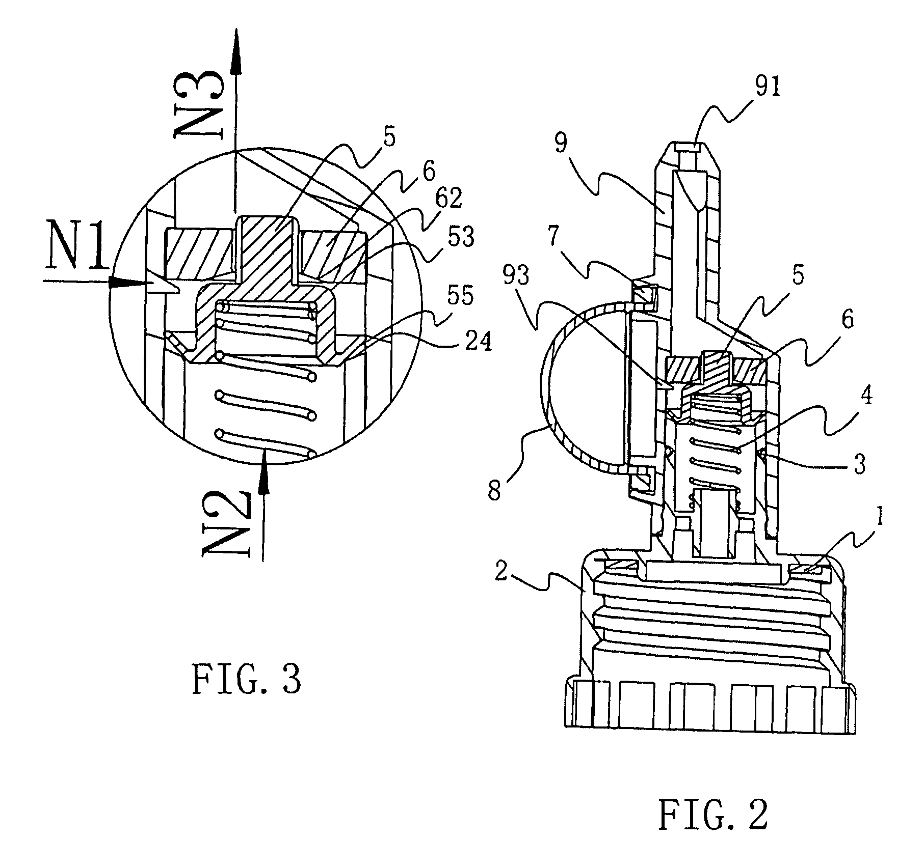
[0036]Please refer to FIG. 1, this novel liquid dispenser mainly includes cover 2, main body 9 and liquid output device comprising button 8, water-sealing ring 6 and spring 4, and valve plate 5 with the effect of a 2-in-1 one-way valve, etc., wherein:

[0037]Cover 2 engages with the opening of the container and in the cover 2 there is a padding piece 1 to ensure it is sealed with the container. On the top of the cover 2 there is a circular tube 21 for connecting to the main body. On the circular tube 21 there is an annular slot 22 for embedding O-shaped sealing ring and an annular flange 23 buckled with the main body.

[0038]The main body 9 is hollow. The inner wall of the lower part of the main body is rotationally engaged with the outer wall of the circular tube 21 of the cover and on the inner wall of the main body 9. There is an annular slot that can connect the main body 9 to the circular tube 21, such as by being buckled with the annular flange 23 of the cover. Said main body 9 is...

embodiment 2

[0043]The liquid dispenser as shown in FIG. 10-FIG. 12, the construction of liquid output device and valve adopted by this embodiment 2 is different from embodiment 1. The liquid output device in this embodiment is composed of button 8, piston 11, water-sealing ring 6 and spring 4, etc. The valve plate 5 also has the function of one-way valve. Its main body is also made into a plate-like shape to match with main body 9. Specifically, the valve plate 5 comprises a circular tube 56 for configuring with piston 11. The outward extension of the circular tube 56 is equipped with a plate-like annular plane 57 which can sealingly engage with the opening 24 of the cover 2. The valve plate 5 is assembled with the piston 11. The piston 11 is coupled through the valve plate 5. The valve plate 5 can close or open the opening 24 of the circular tube 21 of the cover 2. The piston 11 is a component which has a cross-like cross-section area, its upper part is inserted in the opening of the water-sea...

embodiment 3

[0045]This embodiment is modified on the basis of the embodiment 1. By modifying the structure of the valve plate and performing certain adaptive changes to the cover and the main body, the spring and the inner side of the valve plate can be kept out of reach of the liquid when the dispenser is discharging liquid. This can not only increase the flexibility of the product operation but also ensure the liquid quality is not affected and it is also good in terms of safety.

[0046]Specifically, as shown in FIG. 13-FIG. 15, the valve plate 5 as shown in the drawings of this embodiment is made on the basis of the valve plate in the embodiment 1 and further extend upward and downward from its upper part and lower part respectively a circular tube 58, 59, and a chamber 94 is formed in the main body 9 and receivable of the upper circular tube 58. An opening 95 is arranged at the top part of the chamber. The upper circular tube 58 is inserted in the chamber 94 and its outer wall sealingly engag...


PUM


Abstract

A liquid dispenser is described and includes a cover connecting to the opening of a container and a main body connecting to the cover. The main body includes a chamber in communication with the cover and a liquid outlet for liquid discharge, wherein a liquid output device is arranged in the chamber, a button is arranged on the main body for controlling the action of the liquid output device, a one-way valve is arranged in the liquid output device for adjusting the open / close state of a liquid output passage. The liquid dispenser described is novel in design, simple and compact in construction. The liquid dispenser described can employ the operating principle of a one-way valve so as to realize liquid discharge in any direction.

Description

TECHNICAL FIELD[0001]The technical disclosure herein relates to a liquid dispenser. The liquid dispenser described can be installed at the opening of a container, which can be used for holding viscous liquid, for example, medical preparation, shampoo, body wash, hand wash, etc., while the liquid dispenser is used to extract appropriate amount of liquid from the container.BACKGROUND ART[0002]The publicly-known liquid dispenser normally has a liquid output member arranged at the center of a cover mounted at a container opening. A head cap is installed at the upper end of the liquid output member. Using the principle of air pump, i.e. applying a force by a user's hand to press the liquid output member, this publicly-known liquid dispenser makes the liquid in the container flow out via an outlet formed in the head cap. As a result, the user can use one of his palms to receive the liquid flowing out of the outlet while using the other palm to keep pressing the head cap so as to extract a...

Claims


Application Information

Patent Timeline
Patent Type & Authority Patents(United States)
IPC IPC(8): B65D37/00
CPCB05B11/3032B05B11/3036B05B11/3074B05B11/3067B05B11/3064B05B11/1036B05B11/1032B05B11/1064B05B11/1067B05B11/1074
Inventor YUAN, JIANJUN
Owner YUAN JIANJUN
Learn More