Low-speed inerting means and device for using said inerting means for packaging a food product

a technology of inerting means and food products, which is applied in the field of low-speed inerting means and devices for using said inerting means for packaging food products, can solve the problems of unsuitable consumption in the short or medium term, high manufacturing cost of devices and their utilization costs, and increase the risk of oxidation of foodstuffs, so as to preserve foodstuffs from any risk of being oxidized , the effect of minimizing the oxygen content in the head volum

Active Publication Date: 2011-04-26
1 4 VIN
View PDF33 Cites 1 Cited by
  • Summary
  • Abstract
  • Description
  • Claims
  • Application Information

AI Technical Summary

Benefits of technology

[0012]The object of the present invention is to propose low-speed inerting means associated with a device for packaging in an ambient atmosphere to package a foodstuff under an atmosphere that is locally inert, as contrasted with devices that perform such packaging in an atmosphere that is generally or even completely inert, for the purpose of minimizing the oxygen content in the head volume so as to preserve the foodstuff from any risk of being oxidized. In addition, given the above-described phenomena, the device is particularly suitable for packaging wine in receptacles.
[0013]Furthermore, another object of the present invention is to provide a packaging device presenting a small number of stations for the purposes of simplification and of limiting the cost inherent to fabricating and using the device.
[0017]Furthermore, in order to optimize inerting, the hollow duct is looped, with its walls that have pores facing towards the receptacle then defining a closed space capable of surrounding the receptacle. In an advantageous variant of the invention, the looped hollow duct forms a ring. Thus, if the receptacle is a glass, inerting takes place uniformly, thereby maximizing its effectiveness. Nevertheless, depending on the shape of the receptacle, other configurations can be envisaged, e.g. a looped duct having a square shape or indeed two distinct hollow ducts that face each other. Similarly, in a variant of the invention in which the hollow duct is not looped, the hollow duct may for example be U-shaped.
[0025]Furthermore, the foodstuff contained in the receptacle may be constituted in particular by a liquid, a paste, or even a solid, e.g., for example: truffles or salmon tartar. In order to protect and preserve the above-mentioned foodstuffs, it is strongly recommended to isolate them from oxygen. Thus, the present invention is found to be particularly useful and effective.
[0027]Nevertheless, if the foodstuff is a liquid, and most particularly wine, then, in a variant of the invention, the packaging unit includes a filler station that is used during a preliminary stage. Thus, during the preliminary stage, the filler station produces a stream of inert gas and a stream of liquid, the inert gas stream surrounding the liquid stream so as to isolate it from the surrounding atmosphere. The filler station then has first and second orifices for producing respectively the liquid stream and the inert gas stream, the second orifice surrounding the first orifice. In this way, the liquid stream does not come into contact with the surrounding atmosphere during a filling stage, and this is particularly advantageous for a liquid that is sensitive to oxidation phenomena, as is the case for wine.

Problems solved by technology

Oxygen leads to oxidation of wine, thereby making it unsuitable for consumption in the short or medium term.
Although that is effective, the resulting device becomes particularly complicated since it is necessary to enclose the filler, closure, and heat-sealing stations within an enclosure that is saturated in inert gas in order to isolate the various stations from the surroundings and thus from the surrounding atmosphere.
The manufacturing cost of the device and its utilization cost, then become large, in particular because of the large quantities of inert gas that need to be used.
In addition, it is found that the large number of stations needed for performing packaging is disadvantageous in terms of cost, maintenance, and bulk.
Furthermore, since the enclosure needs to be completely filled with inert gas, the time taken for packaging becomes large, which can lead to a non-negligible loss of revenue.

Method used


Image

  • Low-speed inerting means and device for using said inerting means for packaging a food product
  • Low-speed inerting means and device for using said inerting means for packaging a food product
  • Low-speed inerting means and device for using said inerting means for packaging a food product

Examples


Embodiment Construction

[0034]Elements present in more than one of the figures are given the same references in each of them.

[0035]In addition, FIGS. 1 to 9 relate to a packaging unit provided with a filler station and a closure station including inerting means. The unit is thus well adapted in particular for packaging a liquid. Nevertheless, if the foodstuff for packaging is inserted in the receptacle with the help of means other than the filler station, it will readily be understood that the filler station could be omitted from the packaging unit. However, if the operator desires to preserve the filler station, e.g. for a future use, the operator may be content to deactivate it temporarily by using the control means of the device.

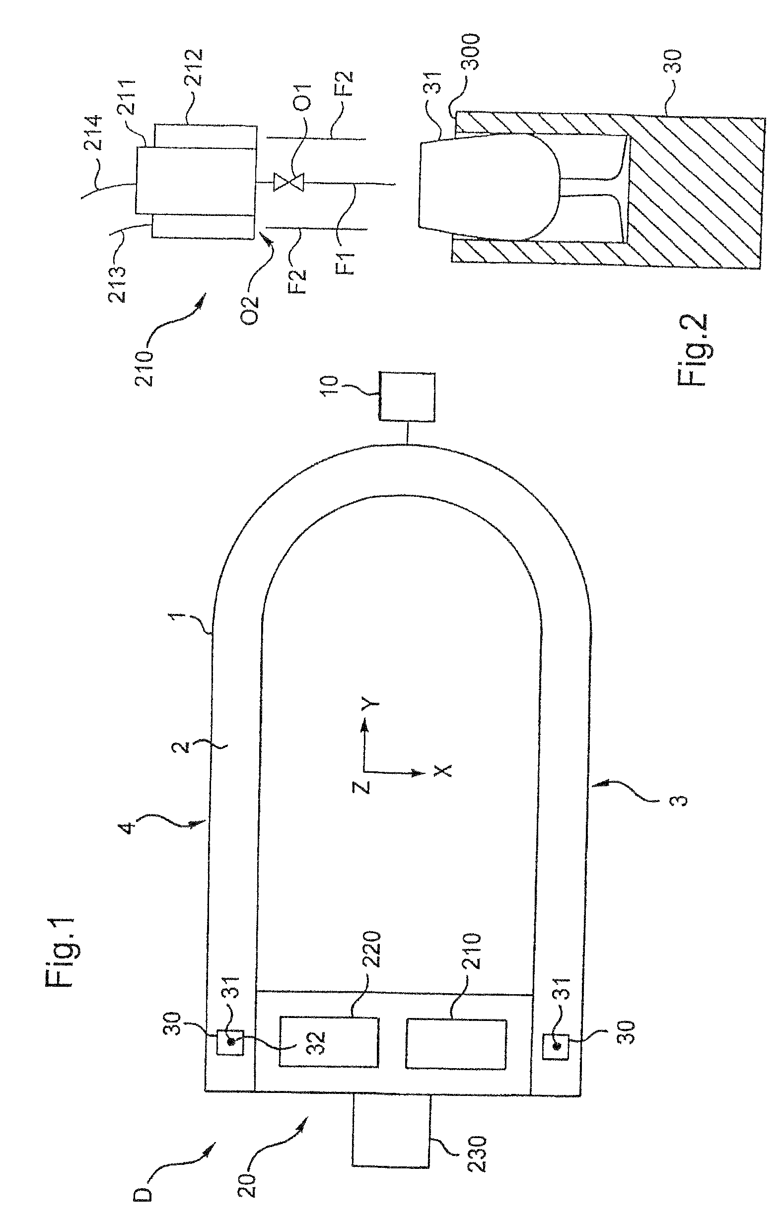
[0036]FIG. 1 is a diagrammatic view showing the device D of the invention as seen looking along the Z axis.

[0037]The device comprises a U-shaped conveyor 1 serving to move receptacles 31, e.g. made of glass or plastics, with the help of the usual means, e.g. an assembly conveyor...


PUM


Abstract

Low-speed inerting elements for depleting a receptacle of oxygen, include at least one hollow duct (2232), with walls (2233) of the hollow duct (2232) that are directed towards the receptacle (31) being made of a material including pores.

Description

[0001]The present application is a National Stage of PCT / FR / 2006 / 001391, filed on Jun. 20, 2006, which claims priority to FR 05 / 06422, filed on Jun. 23, 2005.[0002]The present invention relates to low-speed inerting means and to a device implementing said inerting means for packaging a foodstuff, in particular a liquid such as wine or an analogous beverage.BACKGROUND OF THE INVENTION[0003]Document EP 1 235 501 E1 describes a method of packaging wine in a receptacle closed by a capsule. When implementing that method, the receptacle passes in succession via:[0004]a filler station for filling the receptacle with an inert gas;[0005]a filler station for filling the receptacle with wine;[0006]a station for depositing the capsule on the rim of the receptacle;[0007]a heat-sealing station for sealing the capsule on the receptacle; and[0008]a post-forming station for shaping the margins of the capsule so as to fold them down against the walls of the receptacle.[0009]The purpose of that method...

Claims


Application Information

Patent Timeline
IPC IPC(8): B65B31/00B65B7/28
CPCB65B31/00B65B7/2878B65B7/2807B67C2003/2688
Inventor CARVIN, PASCALMURA, CHRISTIAN
Owner 1 4 VIN
Why Eureka
Try Eureka