Eureka AIR delivers breakthrough ideas for toughest innovation challenges, trusted by R&D personnel around the world.

Laminated film

a technology of laminate film and adhesive, applied in the field of laminate film, can solve the problems of large amount of color shift, light leakage or significant color change, optical unevenness, etc., and achieve the effect of sufficient adhesive force and adhesion time, separation and removal by a small force, and high display uniformity

Inactive Publication Date: 2011-04-19
NITTO DENKO CORP
View PDF16 Cites 30 Cited by
  • Summary
  • Abstract
  • Description
  • Claims
  • Application Information

AI Technical Summary

Benefits of technology

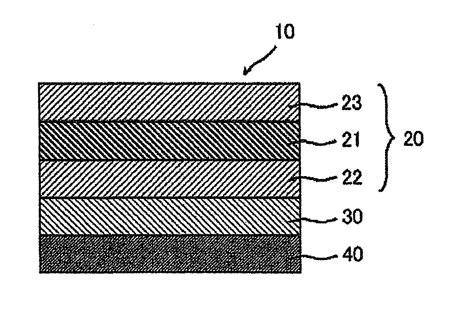
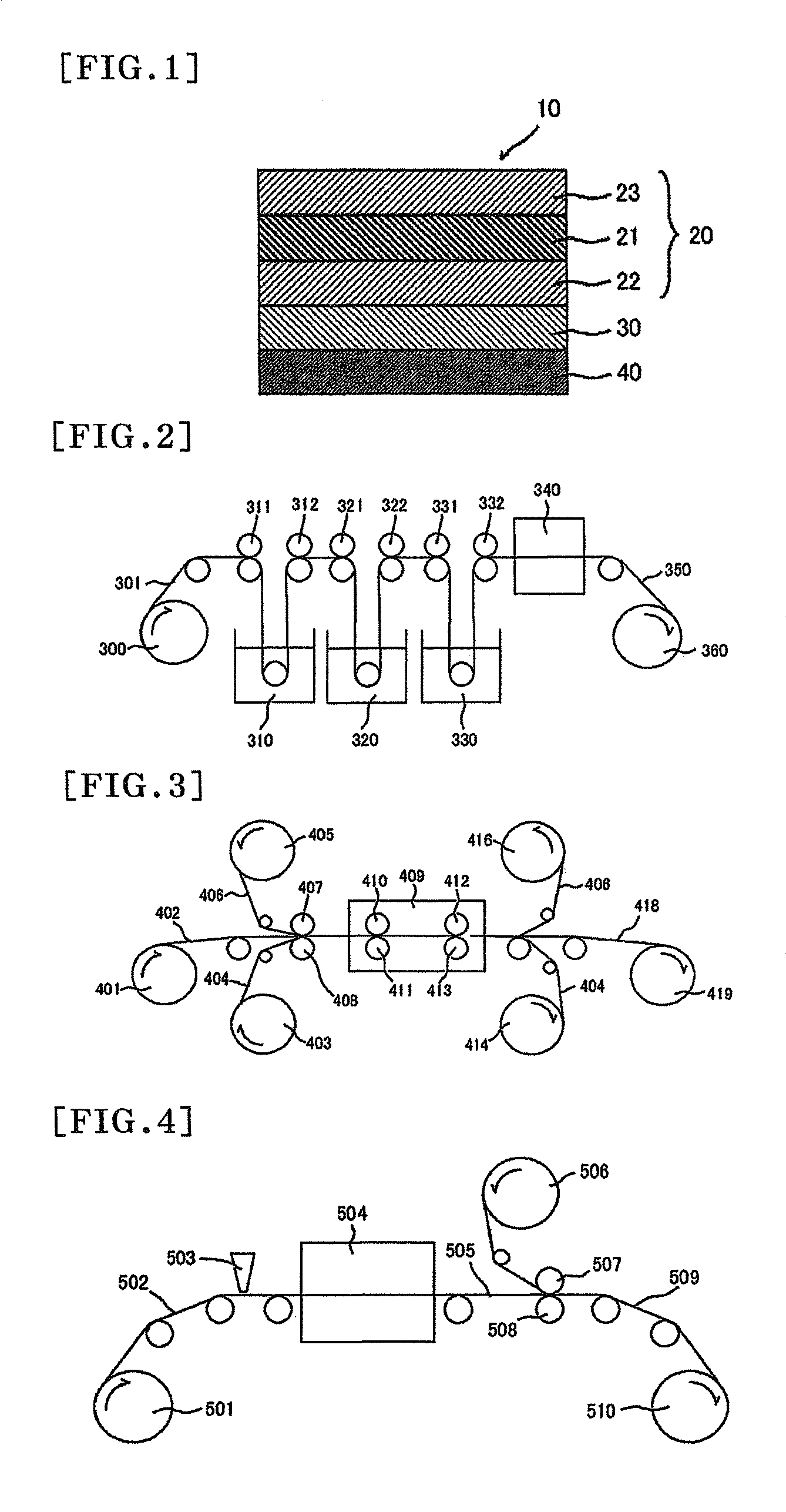
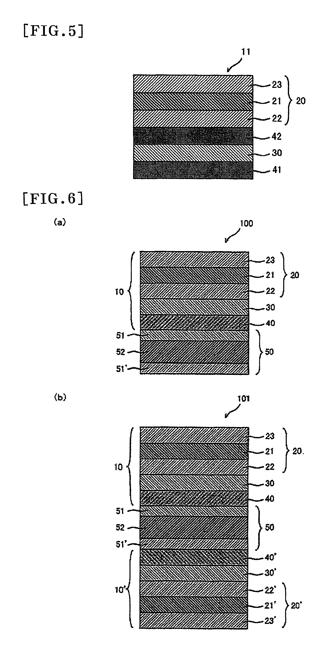
[0028]The laminated film of the invention, has a stretched film comprising a norbornene resin as a retardation film and thus can form a liquid crystal display that can resist distortion-induced optical unevenness and provide a high level of display uniformity. When the retardation film has a refractive index ellipsoid satisfying the relation nx≧nz>ny, amounts of leakage of light in oblique directions and amount of color shift in the liquid crystal display are significantly smaller than those in conventional liquid crystal displays. The laminated film of the invention also uses a pressure-sensitive adhesive that may be produced by crosslinking a specific composition, and thus the pressure-sensitive adhesive can be strongly bonded to the retardation film. In such a liquid crystal display, peeling from a substrate of the liquid crystal cell (glass substrate) or bubbles can be prevented even in a high-temperature, high-humidity environment can provide a practically sufficient level of adhesive force and adhesion time. On the other hand, when the laminated film is peeled off and the liquid crystal cell is recycled, neither pressure-sensitive adhesive layer nor retardation film is left on the surface of the liquid crystal cell, and each optical film can be separated and removed by a small force. Thus, the productivity of the liquid crystal display can be significantly increased with no change in the cell gap of the liquid crystal cell or no damage to the substrate.

Problems solved by technology

However, liquid crystal displays produced with a conventional laminated film cause a problem.
For example, leakage of light or significant changes in color (also referred to as a large amount of color shift) occur depending on the viewing direction, when a black image displayed on a screen is viewed from oblique directions, or optical unevenness is obtained, when backlight is allowed to run for certain hours.
However, a conventional laminated film causes a problem in which the laminated film is difficult to separate from a liquid crystal cell, or a certain component of the laminated film (such as a retardation film or a pressure-sensitive adhesive layer) is left on the surface of a liquid crystal cell after the process of peeling the laminated film.
In conventional technologies, it has been difficult to satisfy such conflicting features at the same time.

Method used


Image

  • Laminated film
  • Laminated film
  • Laminated film

Examples


reference example 1

[0295]A shrinkable film A (a 60 μm-thick, polypropylene-containing, biaxially-stretched film (“TORAYFAN BO 2873” (trade name) manufactured by TORAY INDUSTRIES, INC.) was bonded to both sides of a 100 μm-thick polymer film containing a resin of a hydrogenated ring-opening polymer of a norbornene monomer (a norbornene resin) (“ZEONOR ZF-14-100” (trade name) 1.52 in average refractive index, 136° C. in Tg, 3.0 nm in Re[590], and 5.0 nm in Rth[590], manufactured by OPTES INC.) with an acrylic pressure-sensitive adhesive layer (15 μm in thickness) interposed therebetween. The laminated film was then held in the machine direction of the film by means of a roll stretching machine and stretched to 1.38 times in an air circulation type oven at 146° C. After the stretching, each shrinkable film A was separated together with each acrylic pressure-sensitive adhesive layer so that a retardation film was prepared. The retardation film was named Retardation Film A, and its properties are shown in ...

reference example 5

[0299]A shrinkable film A was bonded to both sides of a 130 μm-thick polymer film (“ARTON FLZU 130D0” (trade name) 78,200 in weight average molecular weight, 1.53 in average refractive index, 135° C. in Tg, 3.0 nm in Re[590], and 5.0 nm in Rth[590], manufactured by JSR Corporation) containing a resin of a hydrogenated ring-opening polymer of a norbornene monomer (norbornene resin) with an acrylic pressure-sensitive adhesive layer (15 μm in thickness) interposed therebetween. The laminated film was then held in the machine direction of the film by means of a roll stretching machine and stretched to 1.38 times in an air circulation type oven at 146° C. After the stretching, each shrinkable film A was separated together with each acrylic pressure-sensitive adhesive layer so that a retardation film (named Retardation Film E) was prepared. Its properties are shown in Table 1. The retardation film had a refractive index ellipsoid satisfying the relation nx>nz>ny, and its wave dispersion (...

reference example 8

[0300]Retardation Film H was prepared using the process of Reference Example 5, except that the draw ratio was 1.43 times and that a shrinkable film B (a 60 μm-thick, polypropylene-containing, biaxially-stretched film) was used instead. Its properties are shown in Table 1. This retardation film had a refractive index ellipsoid satisfying the relation nx>nz>ny, and its wave dispersion (D) was 1.00. The physical properties of the shrinkable film B are shown in Table 2.


PUM

PropertyMeasurementUnit
thicknessaaaaaaaaaa
widthaaaaaaaaaa
Tgaaaaaaaaaa

Abstract

A laminated film includes a polarizing plate, a retardation film, and a first pressure-sensitive adhesive layer provided in this order, wherein the polarizing plate includes a polarizer, a first protective layer placed on a side of the polarizer where the retardation film is provided, and a second protective layer placed on another side of the polarizer which is opposite to the side where the retardation film is provided, the retardation film is a stretched film comprising a norbornene resin,the first pressure-sensitive adhesive layer includes a pressure-sensitive adhesive that may be produced by crosslinking a composition comprising a (meth)acrylate (co)polymer and a crosslinking agent comprising a peroxide as a main component. The laminated film has both good adhesion to a liquid crystal cell and easy peelability, and may improve the uniformity in a screen of liquid crystal display.

Description

TECHNICAL FIELD[0001]The invention relates to laminated film having a polarizing plate, a retardation film, and a pressure-sensitive adhesive layer.BACKGROUND ART[0002]Liquid crystal displays are attracting attention because of their features such as slimness, lightweight and low power consumption and widely used in portable equipment such as cellular phones and watches, office automation equipment such as personal computer monitors and notebook computers, domestic electrical equipment such as video cameras and liquid crystal televisions, and so on. Laminated films including laminate of retardation films and any of various polarizing plates are used in conventional Liquid crystal displays.[0003]For example, a patent document 1 listed below discloses that a liquid crystal display which has a polarizing plate and a retardation film having a refractive index ellipsoid satisfying the relation nx>nz>ny placed on one side of an in-plane switching (IPS) liquid crystal cell, has impro...

Claims


Application Information

Patent Timeline
Patent Type & Authority Patents(United States)
IPC IPC(8): G02F1/1335G02B1/08G02B5/30C09J7/29
CPCB32B27/00C08G18/6229C08G18/6254C08G18/7642C08G18/7843C09J7/0296C09J133/08C09J133/14C09J175/04G02B5/3083G02B27/281G02F1/133528C08G18/61G02F2202/28C08G2170/40C09J2433/00G02F1/13363B32B7/12B32B23/08B32B23/20B32B27/08B32B27/16B32B27/18B32B27/20B32B27/302B32B27/306B32B27/308B32B27/325B32B2270/00B32B2307/308B32B2307/40B32B2307/402B32B2307/418B32B2307/42B32B2307/50B32B2307/514B32B2307/708B32B2307/71B32B2307/718B32B2457/202C09J7/29C09J2203/318
Inventor TOYAMA, YUUSUKESATAKE, MASAYUKIYODA, KENJITOMONAGA, MASATOSHIYANO, SHUUJI
Owner NITTO DENKO CORP
Why Eureka
Eureka Blog
Learn More