
Battery performance monitor

a battery and monitor technology, applied in battery/fuel cell control arrangement, secondary cell servicing/maintenance, instruments, etc., can solve the problems of battery being deemed to be discharged erroneously, actual discharge profile change, measured voltage will be significantly affected, etc., and achieve the effect of improving the equipment for battery evaluation

Active Publication Date: 2011-04-19
BATTERY TECH HLDG
View PDF123 Cites 93 Cited by
  • Summary
  • Abstract
  • Description
  • Claims
  • Application Information

AI Technical Summary

Benefits of technology

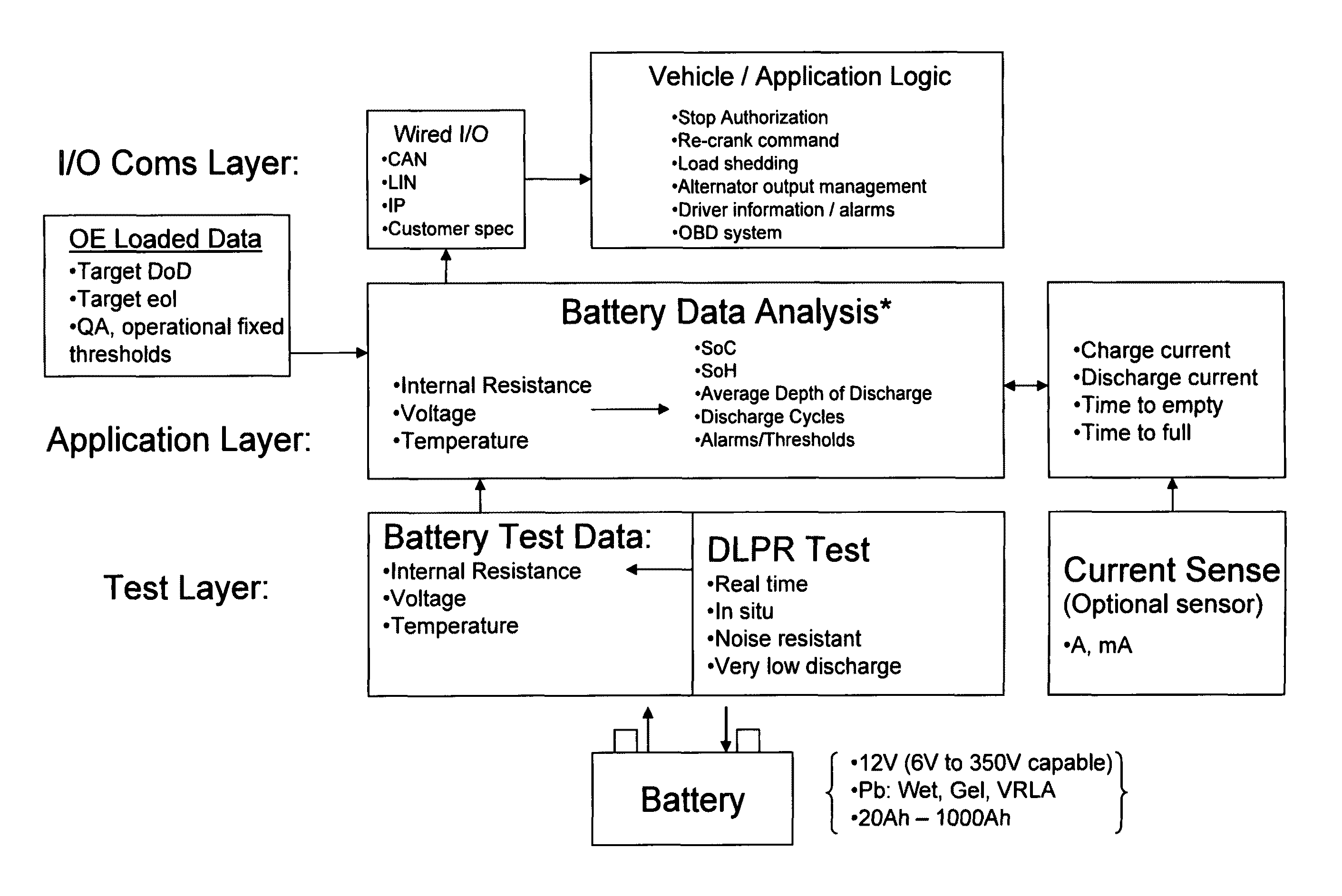
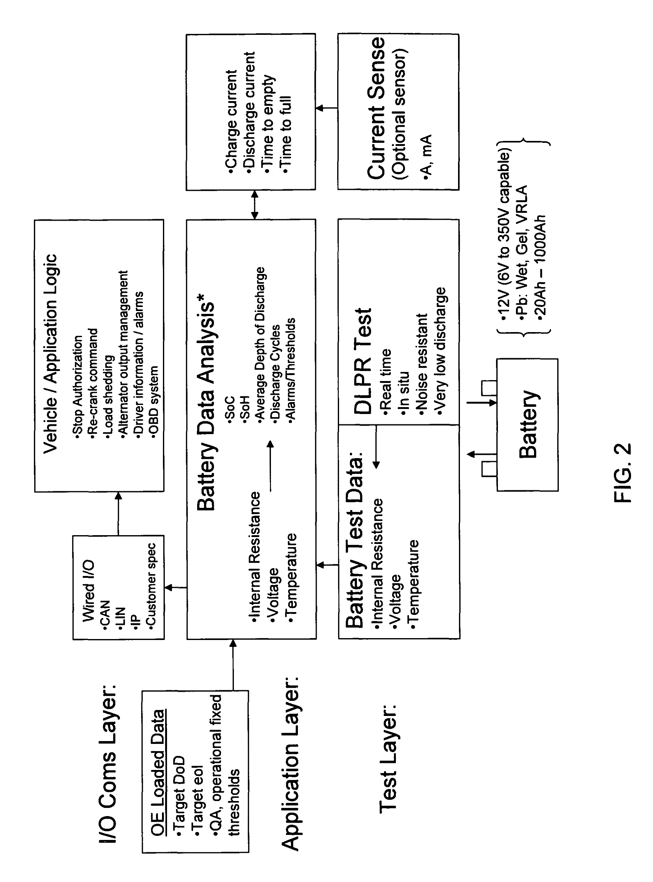
[0055]Accordingly, one object of the invention is to provide a low-cost battery monitor that can readily be retrofit to an existing vehicle, and that is capable of communicating battery status information to, for example, the operator, or to a remote location such as the office of a vehicle fleet manager, to enable proactive measures to be taken where needed.
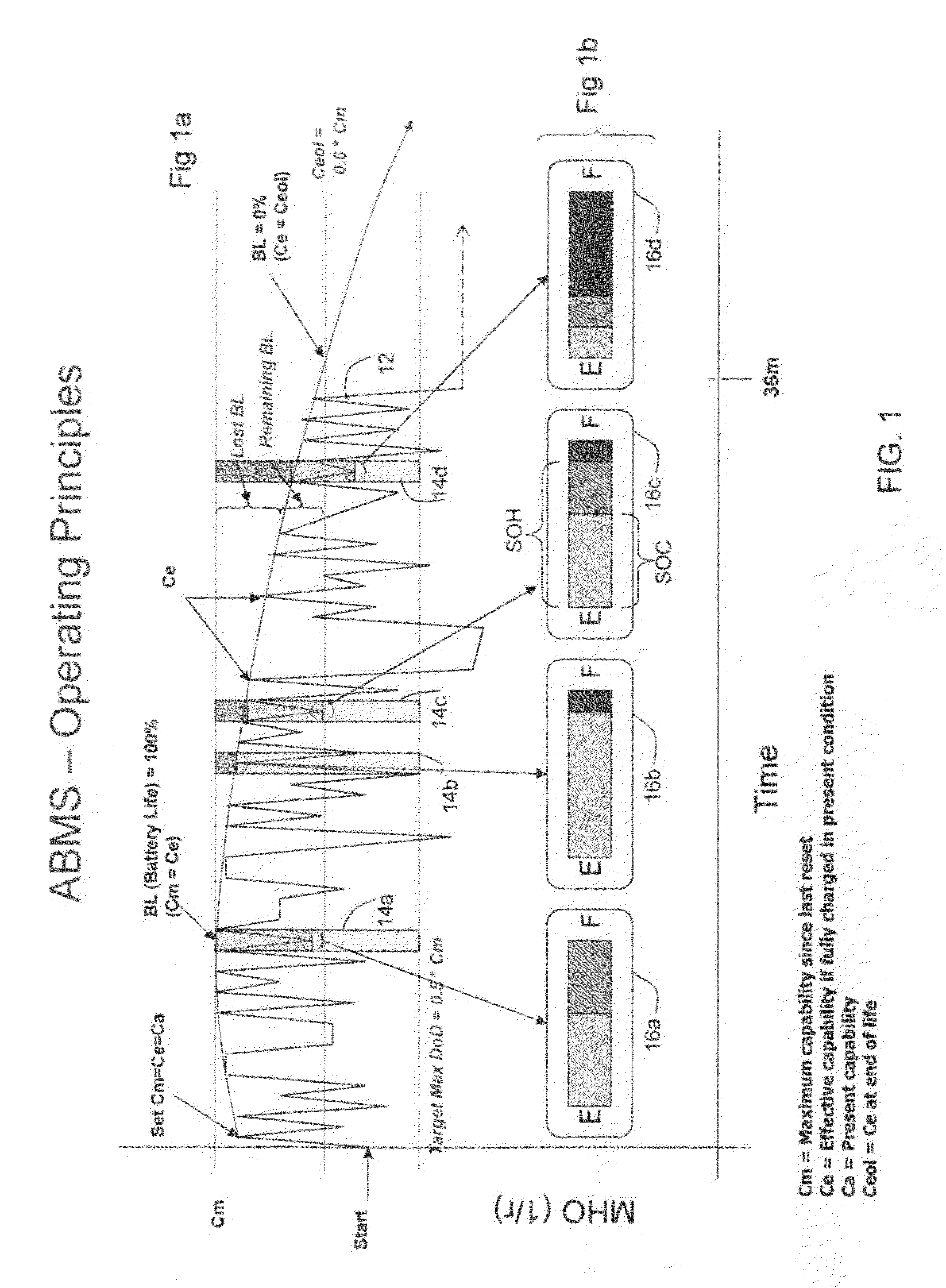
[0056]Another object of the invention is to provide an instrument providing an accurate value for SOC, and that is self-calibrating so as not to be susceptible to long-term drift. Still further, it is an object of the invention to provide such an instrument that is capable of “self-learning” the characteristics of the battery, avoiding the necessity of having the battery characteristics input thereto on installation.
[0057]Another object of the invention is to provide such an instrument that can additionally provide an indication of the battery SOH, so that incipient battery failure can be predicted and thereby avoided.
[0058]Another object of the invention is to provide an instrument for determining the SOH of a battery that would provide an accurate evaluation of its condition, independent of its SOC, and not requiring manual input of nominal characteristics of a comparable new battery of similar specifications for comparison. Such an instrument would be most useful in evaluating used batteries for warranty claims and the like.
[0059]Another object of the invention is to provide a “smart” battery charger, that is, a battery charger capable of accurately evaluating the condition of a battery, in order to adjust the charging parameters accordingly, and further to provide an output indicating that the battery has reached the end of its useful life, when appropriate.

Problems solved by technology

Second, the actual discharge profile changes as the battery ages.
Lastly, the measured voltage will be significantly affected by the load (or charger) applied to the battery.
For example, a fully-charged battery with a large load applied will display a low voltage, so that the battery will erroneously be deemed to be discharged.
Most importantly, this method does not directly measure the level of energy in the battery, but only monitors the flow of energy into and out of the battery, and uses this data to measure departure from a prerecorded reference value.
Over even a few discharge / recharge cycles the resulting estimation of capability drifts substantially and quickly from the actual energy in the battery due to inefficiencies associated with battery charging and discharging that cannot be measured or accurately estimated.
Devices implementing this method are also large and cumbersome to install and connect.
Even with such detail, VIT sensors and the process of current integration over time are inherently prone to accumulated errors.
While a VIT sensor may provide a highly accurate indication of SOC at the start of a measurement cycle, errors accumulate and can become substantial after 10 or 20 discharge cycles and often get worse as the battery ages.
In addition to being prone to accumulated error problems, because of the specific nature of the correction algorithms it is not possible to simply apply a VIT sensor to any battery in any application and expect to get useful SOC or SOH information.
These shortcomings limit the application of VIT sensor technology to very specific applications for which the sensor has been programmed.
These limitations are problematic for car makers and makers of other equipment that offer many models of equipment with many different batteries.
In each case the VIT technology is incapable of accurately measuring SOC.
Thus, the measured voltage response will include significant distortion associated with devices attached to the battery.
This deficiency makes it very difficult for this method to be used for accurately determining the condition of a battery while it is being used.
U.S. Pat. No. 6,424,157 refers to the difficulty of measuring battery SOC from open-circuit voltage (OCV) because this requires that the battery be disconnected.
However, this method is not suitable for measuring the dynamic conductance of a battery in use in the typically electronically “noisy” automotive environment.

Method used


Image

  • Battery performance monitor
  • Battery performance monitor
  • Battery performance monitor

Examples


Embodiment Construction

[0077]The following description of the preferred embodiments of the invention essentially includes the text of provisional application Ser. No. 60 / 935,017, from which the present complete application claims priority, although corrections and clarifications have been made. Following this, there is a detailed discussion of further discoveries and associated improvements made subsequently. Ser. No. 60 / 935,017 and the Appendices with which it was filed are incorporated herein by this reference. Further, applicants reserve their right to submit additional claims to any particulars disclosed therein and not claimed as of the initial filing of this application.

Stand-Alone Engine Starting Battery Monitor

[0078]In one aspect of the invention, a stand-alone apparatus and method of monitoring an engine starting battery are provided. A monitoring device is physically secured to a battery, and is electrically connected to the battery terminals, such that the device can continuously monitor the ba...


PUM

PropertyMeasurementUnit
currentaaaaaaaaaa
currentaaaaaaaaaa
timeaaaaaaaaaa

Abstract

Improvements both in the methods whereby existing techniques for determining the condition of a battery are communicated to a user (for example, to the owner of a private vehicle, or to the service manager of a fleet of vehicles), or the vehicle's operating system, and in the methods for evaluating the condition of the battery are disclosed. It has been discovered by the inventors that the difference in internal resistance of a fully charged battery as measured during charging and as measured after charging is greater for a battery in poor condition than for a new battery. The invention relates in part to instruments and corresponding methods for evaluating the condition of a battery utilizing this discovery.

Description

CROSS-REFERENCE TO RELATED APPLICATION[0001]This application claims priority from U.S. provisional patent application Ser. No. 60 / 935,017, filed Jul. 23, 2007.FIELD OF THE INVENTION[0002]This application relates generally to the field of evaluating the condition of batteries, in particular to evaluation of the state of charge and state of health of storage batteries used in environments where the batteries are subjected to varying loads and recharging sequences, for example in motor vehicle and marine applications.BACKGROUND OF THE INVENTION[0003]1. Overview[0004]The safe and reliable operation of passenger vehicles, commercial trucks, military equipment, boats, aircraft, telecommunications equipment, electric vehicles, computer systems, and many other devices requires predictable and reliable performance of the batteries that are integrated into those systems. The present invention relates to battery monitoring equipment, more particularly to methods and apparatus for monitoring th...

Claims


Application Information

Patent Timeline
Patent Type & Authority Patents(United States)
IPC IPC(8): G01N27/416
CPCB60L11/1857G01R31/3662G01R31/3679B60L11/1861Y02T90/16B60L2250/10B60L2260/46B60L2260/56G01R31/3689G01R31/3693G01R31/3696H01M10/42Y02T10/7005Y02T10/7044Y02T10/705B60L58/15B60L58/16G01R31/364G01R31/3647G01R31/371G01R31/389G01R31/392Y02E60/10Y02T10/70
Inventor HUANG, YUNG-SHENGKALLFELZ, ANDREW F.
Owner BATTERY TECH HLDG
Learn More