Support construction for at least one furniture drive

a technology for supporting construction and furniture, applied in the direction of furniture parts, drawers, domestic applications, etc., can solve the problem that the furniture body does not have a stable rear wall, and achieve the effect of convenient and precise mounting of the supporting construction

Active Publication Date: 2011-04-19
JULIUS BLUM GMBH
View PDF19 Cites 7 Cited by
  • Summary
  • Abstract
  • Description
  • Claims
  • Application Information

AI Technical Summary

Benefits of technology

[0004]It is therefore an object of the present invention to provide for convenient and precise mounting of the support construction at or in a furniture item.
[0006]In that way, it is possible for the holding portions to be fixed to a, preferably stationary, portion of the pull-out-guide assembly (which have already been pre-assembled to the furniture body) and then for the transverse bearer (on or at which at least one furniture drive for ejection of the drawer can be mounted) to be connected to the holding portions. The portion for securing the holding portions to the pull-out-guide assembly is selected such that it predetermines a defined position for the furniture drive having a Touch-Latch functionality. Thereby, it is possible to obtain a defined release path for the Touch-Latch function in order to properly eject the drawer from a closed position. In that way the furniture drive can always be arranged in a precise position with respect to the rear wall of the drawer.
[0010]A further embodiment of the invention provides that the holding portions can be connected with the transverse bearer by a snap-action connection means. The detachable connection of the transverse bearer to the holding portions makes it possible for the transverse bearer to be subsequently connected to the holding portions which have already been pre-assembled. In that context, it may be desirable if the holding portions have a lateral portion for fixing to the pull-out-guide assembly and a transverse portion projecting substantially at a right angle from the lateral portion for connection to the transverse bearer.

Problems solved by technology

In many cases, however, the furniture body does not have a stable rear wall for mounting the furniture drive, so that the use of a transverse bearer or a support rail for mounting the furniture drive has proven to be beneficial.

Method used


Image

  • Support construction for at least one furniture drive
  • Support construction for at least one furniture drive
  • Support construction for at least one furniture drive

Examples


Embodiment Construction

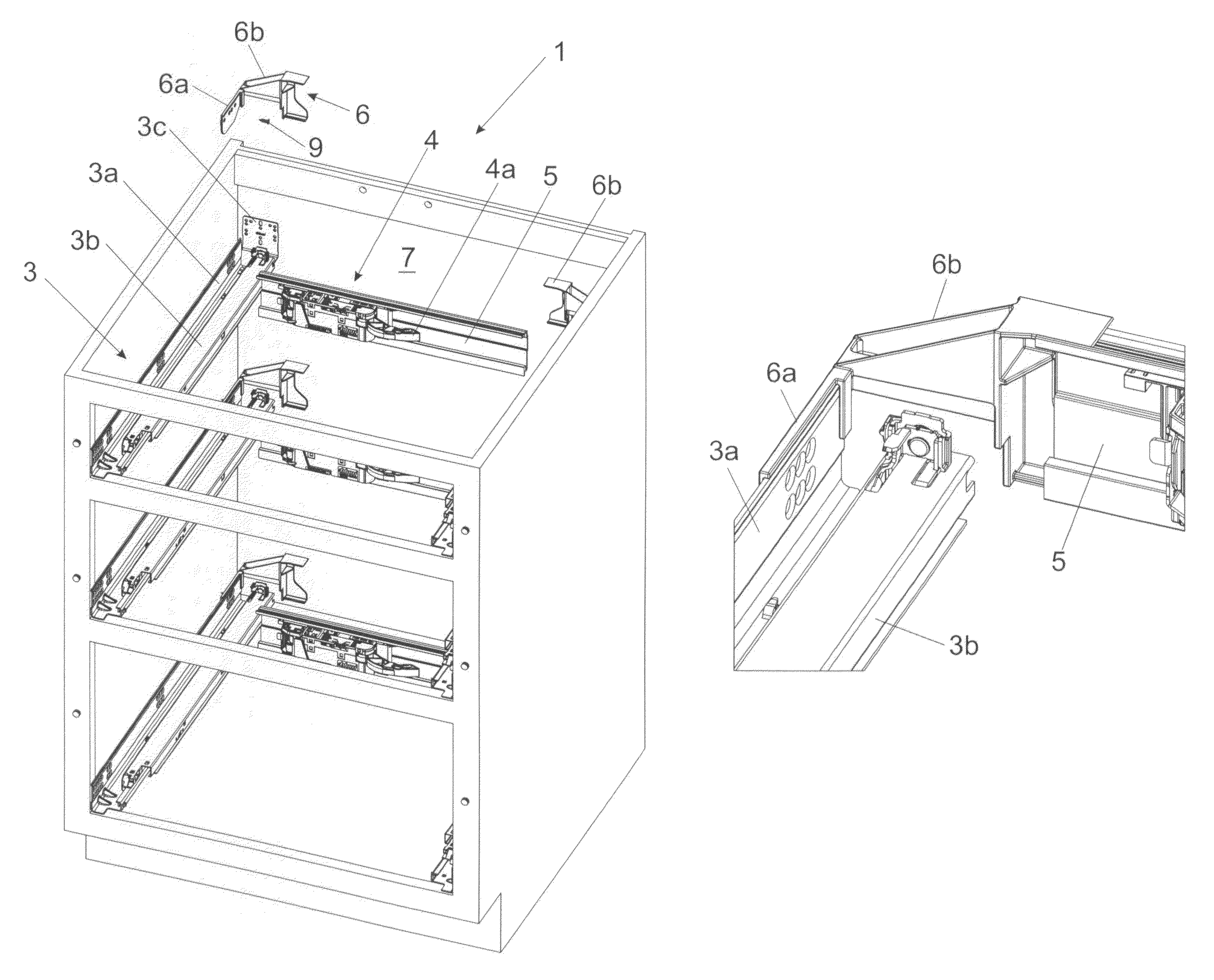
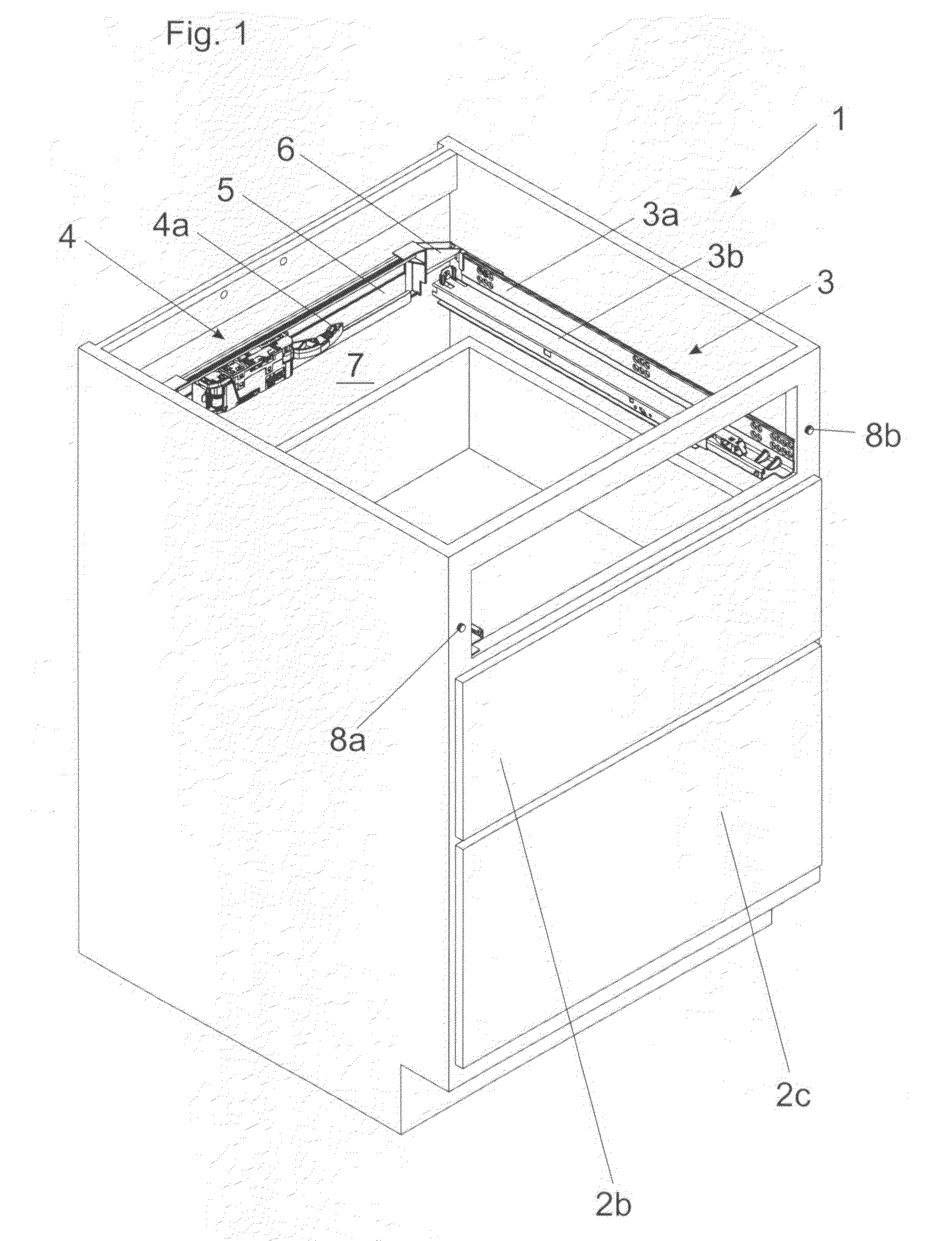
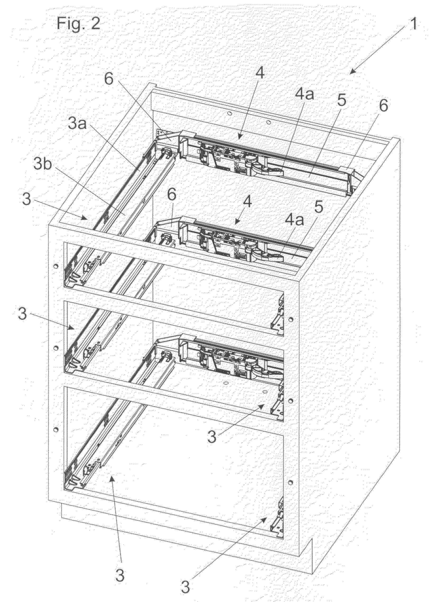
[0020]FIG. 1 shows a perspective view of a furniture item 1 in cupboard form, with displaceable drawers 2b and 2c, the uppermost drawer 2a having been removed for the sake of enhanced clarity of the drawing. Provided at both sides of the respective drawers 2b and 2c are pull-out-guide assemblies 3 for displacing the drawers 2b, 2c, said pull-out-guide assemblies 3 comprise a stationary carcass rail 3a and at least one extension rail 3b which is displaceable relative to the carcass rail 3a. A furniture drive 4 with an ejection element 4a is depicted, by means of which a drawer associated with the ejection element 4a can be moved from the closed position into an open position when manually applying a pushing force or a pulling force to the front panel of the drawer 2b, 2c. The furniture drive 4 is therefore preferably equipped with a Touch-Latch functionality, wherein the ejection element 4a in the form of a pivotally mounted lever presses against the rear wall of the respective drawe...


PUM


Abstract

A support construction is provided for fixing at least one furniture drive for a movable furniture part in a furniture body. The support construction includes two lateral holding portions and a transverse bearer extending between the holding portions. The holding portions have fixing means for preferably releasably fixing the holding portions to a respective pull-out-guide assembly.

Description

BACKGROUND OF THE INVENTION[0001]The present invention relates to a support construction for fixing at least one furniture drive for driving a movable furniture part in a furniture body, wherein the support construction comprises two lateral holding portions and a transverse bearer extending between these holding portions.[0002]Furthermore the invention relates to a furniture item comprising a support construction of the kind to be described.[0003]Support constructions for mounting a furniture drive are used in particular in connection with furniture items in cupboard form having one or more drawers for moving the drawer by means of the furniture drive from a closed position into an open position. For that purpose, the furniture drive is arranged in the immediate proximity of the rear wall of the respective drawer. An ejection element acts on the rear wall of the drawer so that the drawer, starting from a closed position, is urged into an open position. For that purpose, stable moun...

Claims


Application Information

Patent Timeline
IPC IPC(8): A47B95/02
CPCA47B88/0477A47B88/463
Inventor RITTER, THOMAS
Owner JULIUS BLUM GMBH
Why Eureka
Try Eureka