Sealing device with tone wheel

Inactive Publication Date: 2011-04-19
UCHIYAMA MFG
View PDF15 Cites 9 Cited by
  • Summary
  • Abstract
  • Description
  • Claims
  • Application Information

AI Technical Summary

Benefits of technology

[0005]The sealing device of the Patent Document 1 teaches that the sealing performance can be improved by the above constitution without complicating the structure. However, because the above-mentioned labyrinth is provided, grist and dust and water easily enter the space surrounded with the first seal plate and the second seal plate from the labyrinth to be accumulated therein. If such condition is kept for a long time that grist and dust and water are accumulated in the space, the grist and dust and so on move in a slidably contacting portion of the seal lip and the slinger, thereby accelerating wear of the seal lip and deteriorating the durability.
[0008]The present invention is proposed in view of the above-mentioned problems and the object of the present invention is to provide a newly developed sealing device with tone wheel which keeps superior sealing performance, durability, and assembling efficiency with a simple structure.
[0011]According to the objective apparatus to which the sealing device with tone wheel of claim 1 of the present invention is applied, the portion of the slinger and the core member which are positioned outside relative to the sealed portion are generally exposed to the exterior environment depending on the applied place. According to the present invention, a part of the lip portion is formed so as to elastically and slidably contact with the extended end face of the slinger, and the flange like portion is clamped by one of the seal lip portion and the another seal lip portion from inside and outside thereof. Therefore, there is no gap to allow earth and sand, water and grist and dust to be entered in the space surrounded with the slinger and the core member having the seal member when the members may be exposed to the exterior environment, thereby preventing acceleration of abrasion of the seal member located in the space because of the ingress of grist and dust and so on to a slidably contacting portion. Further, a part of the lip portion slidably contacts in an elastic condition with the extended end face of the slinger, so that the contacting force becomes strong, the ingress of grist and dust can be effectively prevented, and the durability of the sealing device is improved.
[0012]Also according to the sealing device with tone wheel of the present invention, the slinger and the elastic seal member are combined together, the outer end of the fitting cylindrical portion of the core member which is outside relative to the sealed portion projects out of the outer surface of the flange like portion of the slinger, and a part of the seal lip portion is formed so as to elastically and slidably contact with an extended end face of the slinger, thereby it is possible that the slinger and the core member provided with the elastic seal member are combined together at first in advance, then the sealing device can be pushed and fixed between the stationary member and the rotary member with an appropriate jig or a tool when the sealing device is assembled, so that the sealing device can be easily assembled.
[0014]When the conventional sealing devices are contacted before being installed in the sealed portion, the sealing devices tend to stick to each other unfavorably due to the magnetic force which occurs between the metallic core member and the tone wheel which is made of the magnetic rubber. However in the case that the base portion of the seal lip portion which elastically and slidably contacts with the extended end face is formed so as to project outside relative to the outer surface of the tone wheel of the present invention, the core member and the tone wheel do not touch each other, thereby the handling of the seal device becomes much easier. Also because the base portion of the seal lip portion is formed so as to project outside relative to the outer surface of the tone wheel, thereby the attack of the grist and dust which comes from outside is decreased even after the seal device is assembled, so that the durability of the seal device is improved.

Problems solved by technology

If such condition is kept for a long time that grist and dust and water are accumulated in the space, the grist and dust and so on move in a slidably contacting portion of the seal lip and the slinger, thereby accelerating wear of the seal lip and deteriorating the durability.
However, assuming that the outer annular body of metal to be provided outside of the sealing device does not exist, the function of preventing the ingress of grist and dust and so on is not achieved at the entrance of the space surrounded with the first sealing portion and the second sealing portion.
However, it does not describe its function nor suggest it elastically and slidably contacts.
Further, the sealing device of the Patent Document 3 has similar problems to the sealing device of the Patent Document 1 mentioned above, because the sealing device with tone wheel of the Patent Document 3 has the similar sealing structure.
Moreover, the handling before the assembling process has been difficult because the seal ring and the slinger are handled separately as mentioned above.

Method used


Image

  • Sealing device with tone wheel
  • Sealing device with tone wheel
  • Sealing device with tone wheel

Examples


embodiment 2

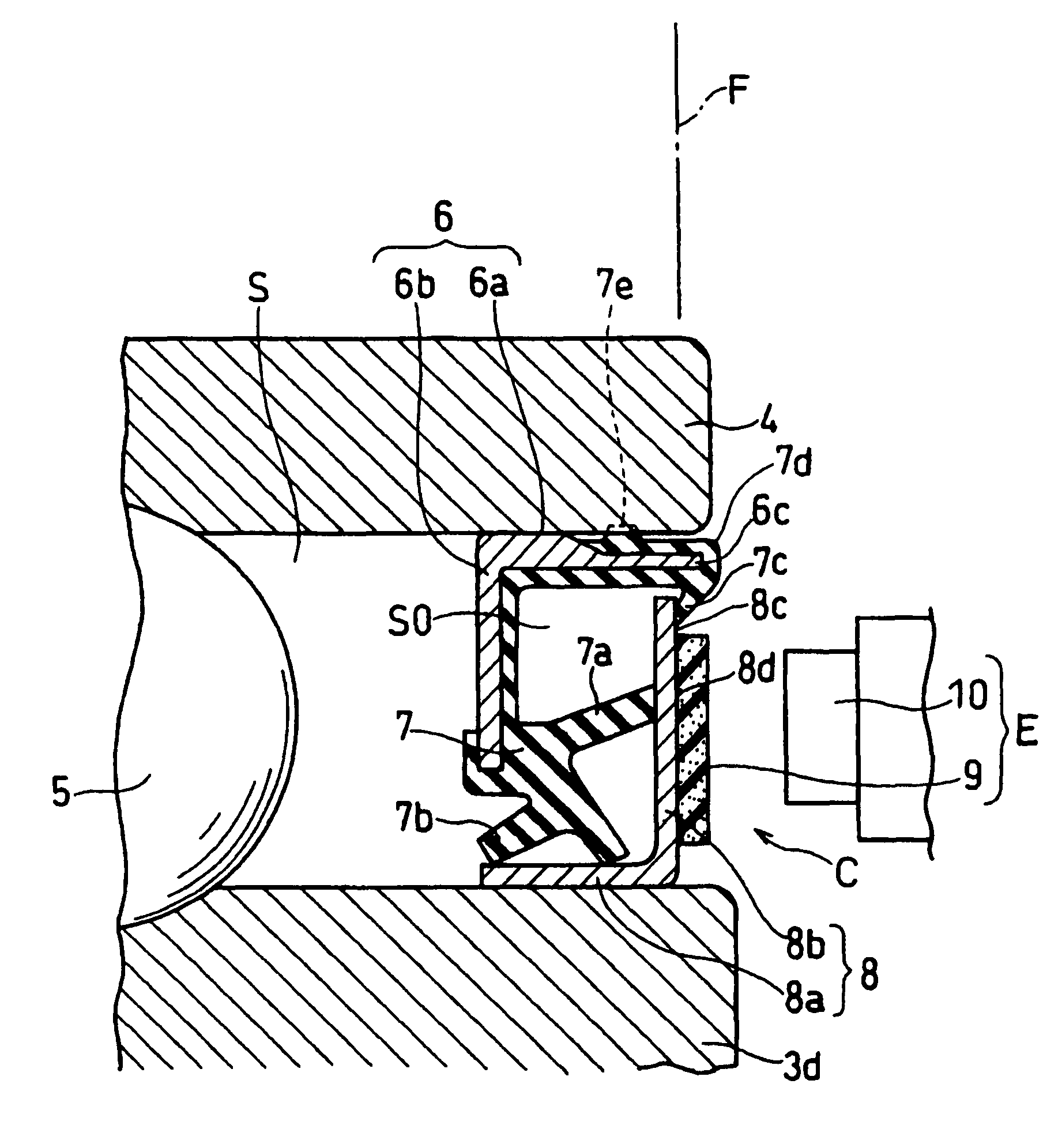
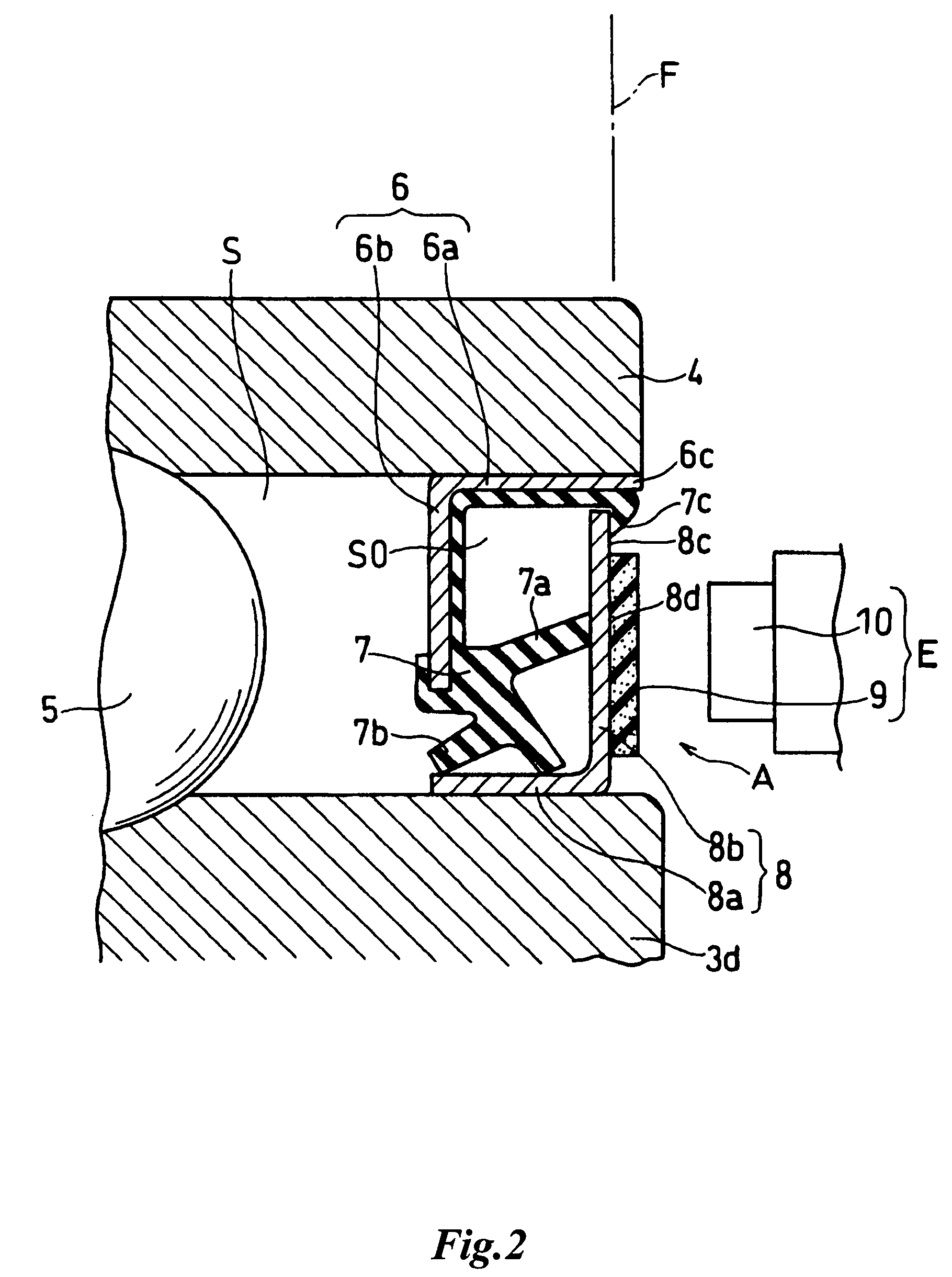
[0029]The seal ring B (sealing device) in FIG. 3 is characterized in that the extended end face 8c of the flange like portion 8b of the slinger 8 is formed as a step portion which shifts to the sealed portion S closer than the attached surface 8d as shown in the figure. The seal lip portion 7c contacts with the step portion constituting the extended end face 8c elastically and slidably from outside. Therefore, the seal lip portion 7c which elastically and slidably contacts with the extended end face 8c can be assembled without touching the tone wheel 9. Also tone wheel 9 can be integrally attached with the attached surface 8d more easily because the surface to be attached with the tone wheel 9 can be recognized easily. Other structures and effects are the same as the above-mentioned embodiment, so the common members have the same reference numerals and their explanations are omitted here.

embodiment 3

[0030]The seal ring C (sealing device) shown in FIG. 4 is characterized in that the base portion 7d of the seal lip portion 7c which elastically and slidably contacts with the extended end face 8c is formed so as to extend outside relative to the outer surface 9a of the tone wheel 9. Therefore the magnetic force of the tone wheel 9 can not make the sealing device C stick to each other, because the core member 6 does not touch the tone wheel 9 even if the sealing device C is contacted each other, so that the handling of the sealing device becomes easier. In addition, because the base portion 7d is formed so as to extend outside relative to the tone wheel 9, therefore the core member 6 and the tone wheel 9 do not touch each other even if the sealing device C is contacted each other as mentioned above, so that the damage of the tone wheel 9 is prevented. Moreover, because the base portion 7d of the seal lip portion 7c is formed so as to extend outside relative to the outer surface 9a o...


PUM


Abstract

A sealing device with a tone wheel formed to seal between a fixed side member and a rotating side member. A slinger comprises a fitting cylindrical part fitted to the rotating side member and a flanged part radially extendedly formed at one end part of the fitting cylindrical part positioned on the outer side of a sealed portion. The outer surface of the flanged part positioned on the outer side of the sealed portion comprises a tone wheel stuck surface on which the tone wheel formed of a magnetic ring is stuck integrally with each other and an extended surface on which the tone wheel is not stuck and extended to the fixed side member. The sealing device is characterized in that a core comprises at least a fitting cylindrical part fitted to the fixed side member, the one end part of the fitting cylindrical part positioned on the outer side of the sealed portion is projected from the outer surface of the flanged part of the slinger to the outside, a part of the seal lip part is formed to be brought into elastically slidable contact with the extended surface of the slinger from the outside, and the flanged part is held by the seal lip part and the other seal lip part from the inside and the outside.

Description

TECHNICAL FIELD[0001]The present invention relates to a sealing device with tone wheel interposed into a necessary portion to be sealed between a stationary member and a rotary member like a bearing unit of a wheel suspension of vehicles, more particularly relates to a sealing device with tone wheel constructed such that a slinger is assembled with a core member for fixedly holding an elastic seal member which elastically and slidably contacts with the slinger, and the slinger is integrally attached with a tone wheel which constitutes a magnetic encoder with a magnetic sensor fixed to the side of the stationary member.BACKGROUND OF THE INVENTION[0002]Such a sealing device with a tone wheel or a sealing device without a tone wheel has been disclosed in the following: JP-A-2001-65704 (Patent Document 1), JP-A-2003-106464 (Patent Document 2), and (Patent Document 3). The Patent Document 1 discloses a sealing device comprising a first sealing plate and a second sealing plate, one of the...

Claims


Application Information

Patent Timeline
IPC IPC(8): F16J15/32F16C41/00F16C33/78F16J15/3232F16J15/326G01P3/487
CPCF16C33/7883F16C41/007G01P3/443G01P3/487F16J15/326F16C2326/02F16C19/186
Inventor SHIBAYAMA, MASANORISENO, HIROSHI
Owner UCHIYAMA MFG
Why Eureka
Try Eureka