
Hand-held power tool with air spring percussion mechanism, linear motor, and control process

a technology of air spring and percussion mechanism, which is applied in the direction of portable percussive tools, drilling machines and methods, dynamo-electric machines, etc., can solve the problems of rotor and the problem of reversal points that are not identically spatially positioned, impede the stable regulation of the movement of the rotor, and the problem of reversal points that are still persisting, so as to reduce the motor model or measurement data array, the effect of low heat loss

Active Publication Date: 2011-04-19
HILTI AG
View PDF9 Cites 37 Cited by
  • Summary
  • Abstract
  • Description
  • Claims
  • Application Information

AI Technical Summary

Benefits of technology

The invention is a hand-held power tool with a linear motor and an air spring percussion mechanism driven by a rotor that can be pressed against a contact element using electromagnetic force. The tool has sensors to determine the position of the rotor and uses a delay step to control the movement of the rotor and position it accurately. The tool is designed to be robust and reliable under real-life operating conditions. The control process is simple and robust. The contacts are made of a cross-linked elastomer that is resistant to high temperatures and fatigue. The tool has a narrow blowhole to ensure constant air volume and a ventilation opening for cooling the air spring. The delay step allows for precise control of the rotor position and can be actively or passively controlled. The invention provides a hand-held power tool with improved performance and reliability.

Problems solved by technology

The fact that there is no positive guidance of the driving piston carried out by a mechanism in the kinematics of the driving piston impedes a stable regulation of the movement of the rotor that is constructed as a driving piston because the reversal points of the movement are not identically positioned in every stroke period.
Therefore, even when an additional holding coil is used, the problem of the absence of a mechanical positive guidance of the rotor and the problem of reversal points that are not identically spatially positioned still persist.
The loose coupling does occasionally cause a decoupling of the complex kinematics, but at the expense of an additional regulation of the coupling process itself; in particular, the rotor must be additionally accelerated and braked.

Method used


Image

  • Hand-held power tool with air spring percussion mechanism, linear motor, and control process
  • Hand-held power tool with air spring percussion mechanism, linear motor, and control process
  • Hand-held power tool with air spring percussion mechanism, linear motor, and control process

Examples


Embodiment Construction

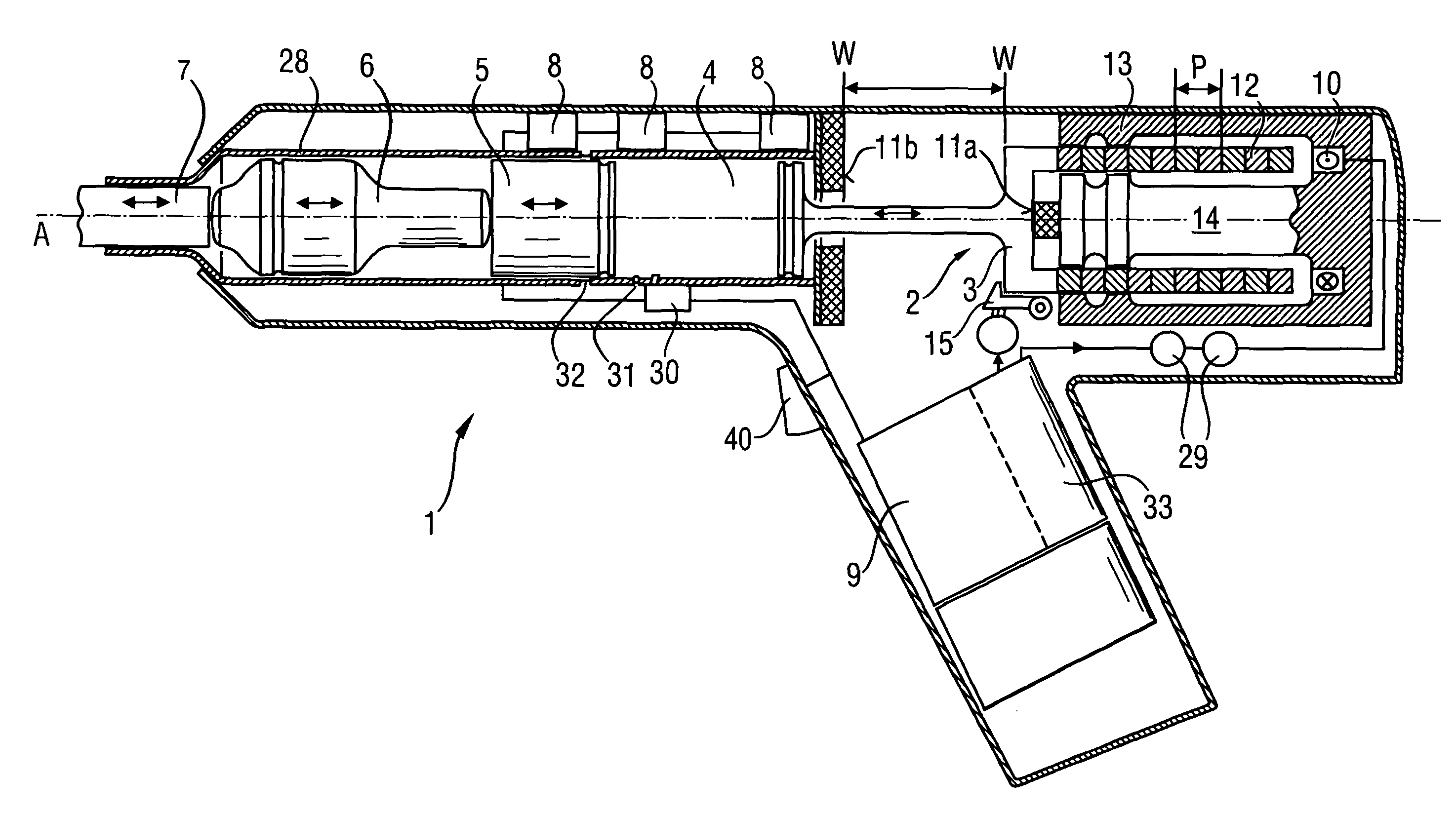
[0062]According to FIG. 1, a hand-held power tool 1, which applies blows along a percussion axis A, includes a linear motor 2 with at least one field coil 10 and whose rotor 3, which is movable in a limited manner axially between two reversal points W, drives a striking piston 5 via an air spring 4. The striking piston 5 applies blows to located axially downstream, impact means in the form of an anvil 6 which applies blows to a tool 7. Sensors designed for determining the actual movement state l(x(t), v(t), a(t)) of the rotor 3 and of the striking piston 5 in the form of, respectively, an axially oriented Hall sensor array 8 for detecting the position of the rotor 3 and striking piston 5, current and voltage sensors 29 for the field coil 10, and a pressure sensor 30 that opens toward the air spring 4 are connected via electronic computing means 9 with power electronics 33 to the field coil 10 of the linear motor 2. The rotor 3 is displaceable, within the two reversal points W locate...


PUM

PropertyMeasurementUnit
speedaaaaaaaaaa
distanceaaaaaaaaaa
delay timeaaaaaaaaaa

Abstract

A hand-held power tool (1) includes a linear motor (2) having a rotor (3) which is movable along a percussion axis (A) in an axially limited manner between two reversal points (W) and which can be driven by the striking piston (5) of the power tool with the intermediary of an air spring (4), sensors designed for determining the actual state of the rotor (3) and connected to a computer (9) connected via power electronics (33) to at least one field coil (10) of the linear motor (2), with the rotor (3) being displaced against a contact element (11a, 11b) at least at one reversal point (W) and being pressed against the contact element electromagnetically; and a control process for the hand-held power tool.

Description

BACKGROUND OF THE INVENTION[0001]1. Field of the Invention[0002]The invention relates to a hand-held power tool with an air spring percussion mechanism which is driven by a linear motor, such as a hammer drill or chisel hammer, and to an associated control process.[0003]2. Description of the Prior Art[0004]For the proper use of percussion hand-held power tools, a stable percussion operation must be ensured over all load ranges and also the transition from percussion operation to impactless idle stroke operation must be ensured when the tool is lifted from a workpiece. Reliable operation of the hand-held percussion power tool must be ensured under every operating condition that is selected in practice by the user. In particular, the following operating conditions can be specified by the user:[0005]the hand-held power tool is switched off and the linear motor is not in operation; the linear motor is in operation, but the tool is not in contact with the workpiece;[0006]the linear motor...

Claims


Application Information

Patent Timeline
Patent Type & Authority Patents(United States)
IPC IPC(8): B25D13/00
CPCB25D11/005B25D11/064H02P25/06H02K33/16B25D2250/035B25D2250/221H02K7/145H02K11/0073H01F7/1844H02K11/33
Inventor JOHN, ALEXANDERSANDER, BERNHARDBINDER, ALBERT
Owner HILTI AG
Learn More