
Adjustable support stand for pre-cast concrete wall forms

a technology of pre-cast concrete and support legs, which is applied in the direction of filing appliances, curtain suspension devices, manufacturing tools, etc., can solve the problems of adding some complexity to the stabilization of forms, uneven production plant floors, and fixed length support legs that may not provide the proper support of the movable steel beam frame to maintain the planar configuration of pre-cast walls to be constructed

Active Publication Date: 2011-04-12
SUPERIOR WALLS OF AMERICA
View PDF35 Cites 15 Cited by
  • Summary
  • Abstract
  • Description
  • Claims
  • Application Information

AI Technical Summary

Benefits of technology

"The invention is an adjustable support stand for pre-cast concrete wall panel forms. It includes a frame portion and a leg member that can move relative to the frame portion. The stand has a floor engaging foot that can be positioned vertically, regardless of variations in the production plant floor. The stand also has a clamping apparatus that can secure the stand to the steel beam frame member of the form. The actuator member can be powered or manually operated, and the stand is durable, inexpensive, and easy to assemble and use. The technical effects of the invention include improved efficiency and accuracy in the leveling and support of pre-cast concrete wall panels."

Problems solved by technology

The utilization of a laterally movable side member, however, adds some complexity in the stabilization of the forms, as well as maintaining a planar configuration so that the pre-cast concrete walls manufactured therefrom are constructed in a planar shape for proper assembly at the job site.
Production plant floors are typically uneven.
Thus, when the laterally movable side member is re-positioned to create a pre-cast wall panel that has a different width than the previous one constructed from the form, a fixed length support leg may not provide the proper support of the movable steel beam frame to maintain a planar configuration of the pre-cast wall to be constructed.
Thus, when the movable side member is re-positioned, shimming the support leg to maintain proper positioning of the movable side member results in lost production time.

Method used


Image

  • Adjustable support stand for pre-cast concrete wall forms
  • Adjustable support stand for pre-cast concrete wall forms
  • Adjustable support stand for pre-cast concrete wall forms

Examples


Embodiment Construction

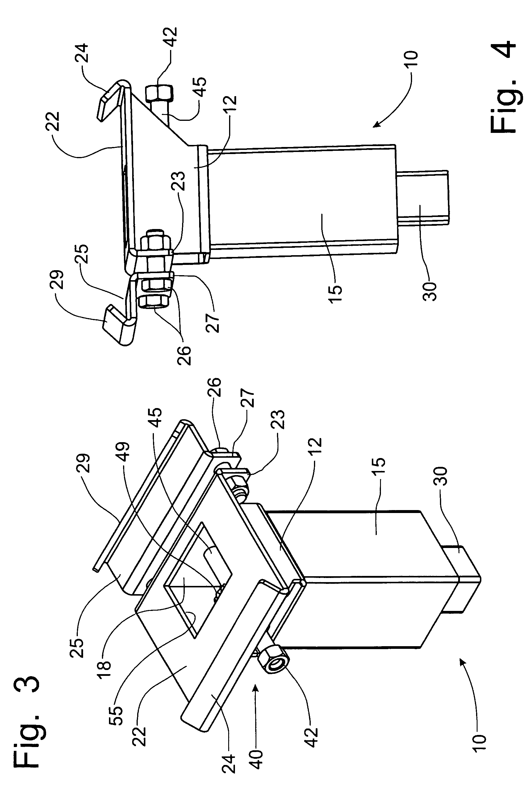
[0040]Referring to FIGS. 1-7, an adjustable support stand, incorporating the principles of the instant invention, for mounting on a steel beam frame member of a form used to manufacture a pre-cast concrete wall panel member can best be seen. The steel beam 5 is shown in FIGS. 1 and 2 and represents a conventional form assembly for a pre-cast concrete wall panel (not shown), as is known in the art. An example of a pre-cast concrete wall panel (not shown) can be found in U.S. Pat. No. 6,494,004, issued to Melvin M. Zimmerman on Dec. 17, 2002, the contents of which are incorporated herein by reference. The adjustable support stand 10 has particular use on a form assembly that incorporates a laterally movable side member (not shown) that can be positioned relative to the rest of the form structure to select the width of the pre-cast concrete wall panel being manufactured in the form. Such a form assembly with a laterally movable side member is known in the art.

[0041]The adjustable suppo...


PUM

PropertyMeasurementUnit
movementaaaaaaaaaa
lengthaaaaaaaaaa
rotationaaaaaaaaaa

Abstract

An adjustable support stand is mounted on a pre-cast concrete wall panel form to facilitate the leveling of the form and the support of the form about the production plant floor. The adjustable support stand includes a frame portion that houses a threaded rod positional fixed for rotation within the frame portion to drive a vertical movement of the leg member in response to rotation of the threaded rod. The adjustable support stand further includes a clamping apparatus that detachably mounts the frame portion to the flanges of a steel beam frame member. The actuator member can be a nut welded to the top of the threaded rod to affect movement of the engaged leg member in response to manipulation with a powered or manually operated hand tool, or a gear set and an orthogonal drive shaft that transfers rotation from a hand tool to the threaded rod.

Description

FIELD OF THE INVENTION[0001]The present invention relates generally to the pre-cast concrete wall systems and, more particularly, to a support stand that locates the forms for manufacturing pre-cast concrete walls in an elevated position above the floor.BACKGROUND OF THE INVENTION[0002]Pre-cast concrete wall systems are known in the art, as can be found, for example, in U.S. Pat. No. 6,494,004, issued to Melvin Zimmerman on Dec. 17, 2002. Such pre-cast concrete walls are typically used as basement walls for building structures, for example, houses and commercial buildings. Such walls are manufactured in a production plant by assembling non-concrete components into a form and pouring concrete into the form to encapsulate the non-concrete components. Once the concrete has hardened, the manufactured wall is stripped away from the form and the wall panel is transported to the job site for installation. Typically, a plurality of wall panels is assembled on the job site to form a basement...

Claims


Application Information

Patent Timeline
Patent Type & Authority Patents(United States)
IPC IPC(8): E04G11/00B28B7/22A47F5/10
CPCB28B7/0032B28B7/0014
Inventor MARTIN, STEVEN L.
Owner SUPERIOR WALLS OF AMERICA
Learn More