
Room arrangement, ship, building and method for constructing a room arrangement

a technology for building and room arrangement, which is applied in the direction of floating buildings, building components, vehicles, etc., can solve the problems of occupying space, reducing the need reducing the need for cabin finishing work, so as to reduce the need for construction work at the shipyard, the effect of improving the quality and productivity of work

Active Publication Date: 2011-04-12
STX FINLAND OY +1
View PDF58 Cites 14 Cited by
  • Summary
  • Abstract
  • Description
  • Claims
  • Application Information

AI Technical Summary

Benefits of technology

This approach reduces material and weight requirements, enhances acoustic and thermal insulation, and facilitates faster, more economical construction of multi-storey structures with improved soundproofing and fire safety, allowing for the creation of taller or more densely packed rooms without the need for continuous load-bearing decks.

Problems solved by technology

One drawback of the known prior art is, that a load-bearing base, onto which base the prefabricated room unit is installed, such as an intermediate deck of a ship or a floor structure of a building, is needed under each prefabricated room unit.
They also take space, and are extremely heavy structures.
Also load-bearing vertical structures, for example load-bearing walls and columns take space and increase the weight of a ship or a building.
The publication in question does not provide a solution for enabling connecting of more than two room units to each other in vertical direction so that the lower room units would sustain the gravity caused by the upper room units.
In order to solve the disadvantages of the prior art, solutions have been suggested, but it has not been possible to eliminate heavily structured ship decks, for example.
It is difficult to come up with a solution for acoustic and heat insulation of heavy hull structures, especially with strictly limited use of space.

Method used


Image

  • Room arrangement, ship, building and method for constructing a room arrangement
  • Room arrangement, ship, building and method for constructing a room arrangement
  • Room arrangement, ship, building and method for constructing a room arrangement

Examples


Embodiment Construction

OF THE FIGURES

[0081]For the sake of clarity, some corresponding parts have the same reference numerals. Further for the sake of clarity, some dimensions in the figures are distorted.

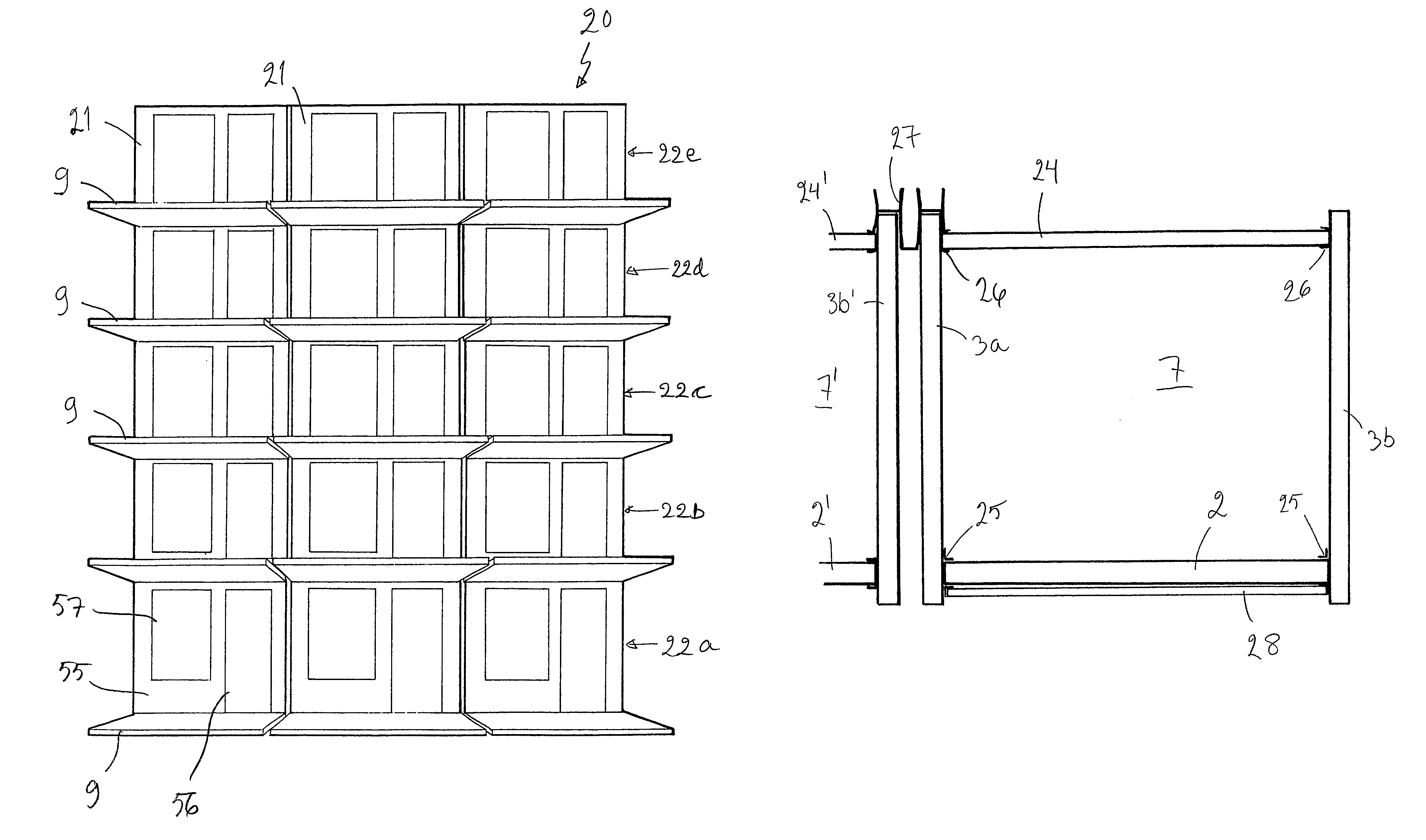
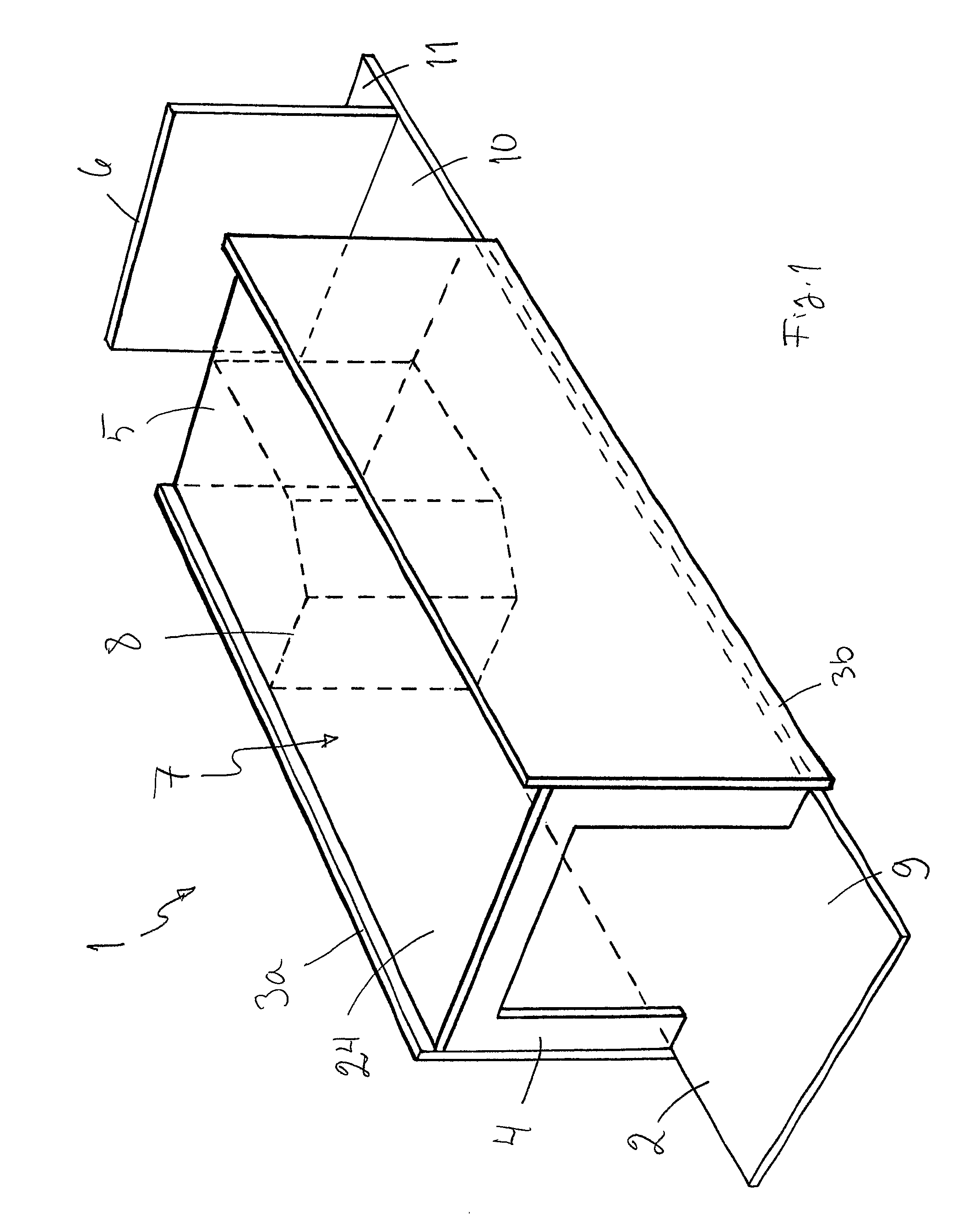
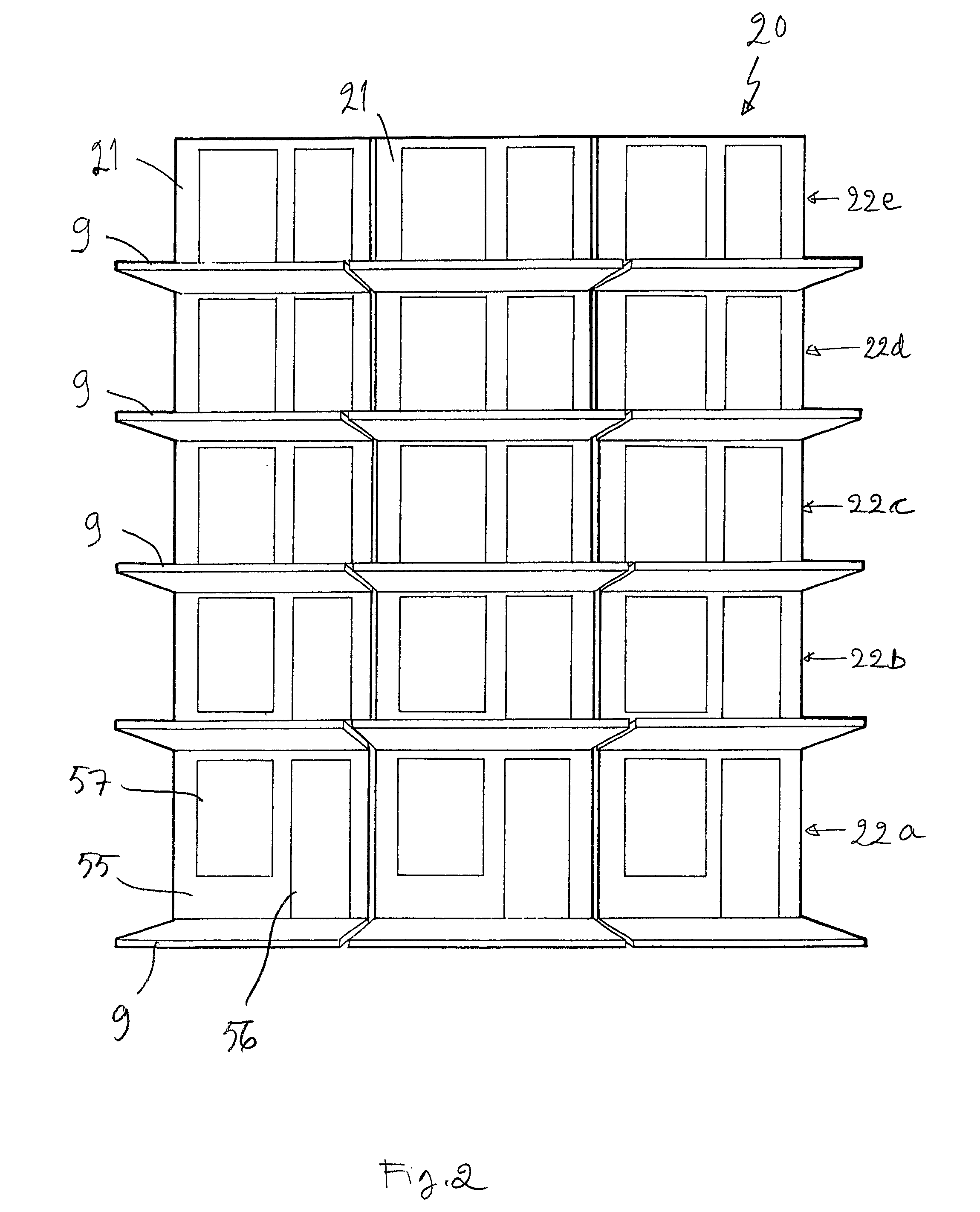
[0082]FIG. 1 shows a room unit 1 according to the invention. The room unit 1 has a floor plate 2, ceiling 24, sidewall panels 3a and 3b, outer wall panels 4, corridor wall panels 5 and another corridor wall panel 6, which are made of cellular board of steel. The wall panels 3, 4 and 5 and the ceiling 24 limit the space above the floor panel 2 to a room 7, such as a ship cabin. Inside the room, a bathroom 8 is shown in broken lines. The floor panel 2 extends to both sides of the outer wall 4 and the corridor walls 5 and 6. External parts of the floor of the room 7 form a balcony floor 9, corridor floor 10 and engineering and utility services room floor 11. The balcony floor 9 and the outer wall panel 4 have been coated by stainless steel for improving their weather resistance. The floor 2 of the room unit...


PUM


Abstract

Room arrangements include at least two superposed prefabricated load-bearing room units. The room units have a ceiling, a floor and at least two walls that are made at least mainly of cellular board. Ships, buildings and methods for constructing a room arrangement are also provided, especially the construction of multi-storey rooms, for example, cabin compartments in ships or block of flats without middle decks or intermediate floors.

Description

[0001]This application is the US national phase of international application PCT / FI2006 / 000022 filed 30 Jan. 2006 which designated the U.S. and claims benefit of FI 20050095, dated 28 Jan. 2005, the entire content of which is hereby incorporated by reference.TECHNICAL FIELD OF THE INVENTION[0002]The object of the invention is a room arrangement, ship, building and method for constructing a room arrangement according to the preambles of the independent claims presented below. The invention relates especially to a new manner of constructing multi-storey rooms, ship cabin compartments or block of flats, for example.PRIOR ART[0003]It is known to bring ship cabins as prefabricated cabin modules to a shipyard, where the cabin modules are installed into a ship. In ships, the cabin modules are installed on some load-bearing base, such as a bottom, intermediate decks or a main deck of the ship. Usually, there are no floors in the prefabricated cabins to be installed into ships, since the dec...

Claims


Application Information

Patent Timeline
Patent Type & Authority Patents(United States)
IPC IPC(8): E04B1/348E04B1/38B63B29/02E04B2/74
CPCB63B29/025E04B1/3483E04B2/7412B63B2231/34E04B1/348
Inventor KORDELIN, TAPIO
Owner STX FINLAND OY
Learn More