
Method for defining animation parameters for an animation definition interface

a technology of animation definition and animation parameters, applied in the field of defining animation parameters for an animation definition interface, can solve the problems of cumbersome and time-consuming, proprietary model animation is not compatible with mpeg-4 requirements, current implementation and modification of animation parameters, etc., and achieves the effect of easy and inexpensive implementation, and easy and inexpensive implementation

Inactive Publication Date: 2011-04-05
AT&T INTPROP II L P
View PDF20 Cites 13 Cited by
  • Summary
  • Abstract
  • Description
  • Claims
  • Application Information

AI Technical Summary

Benefits of technology

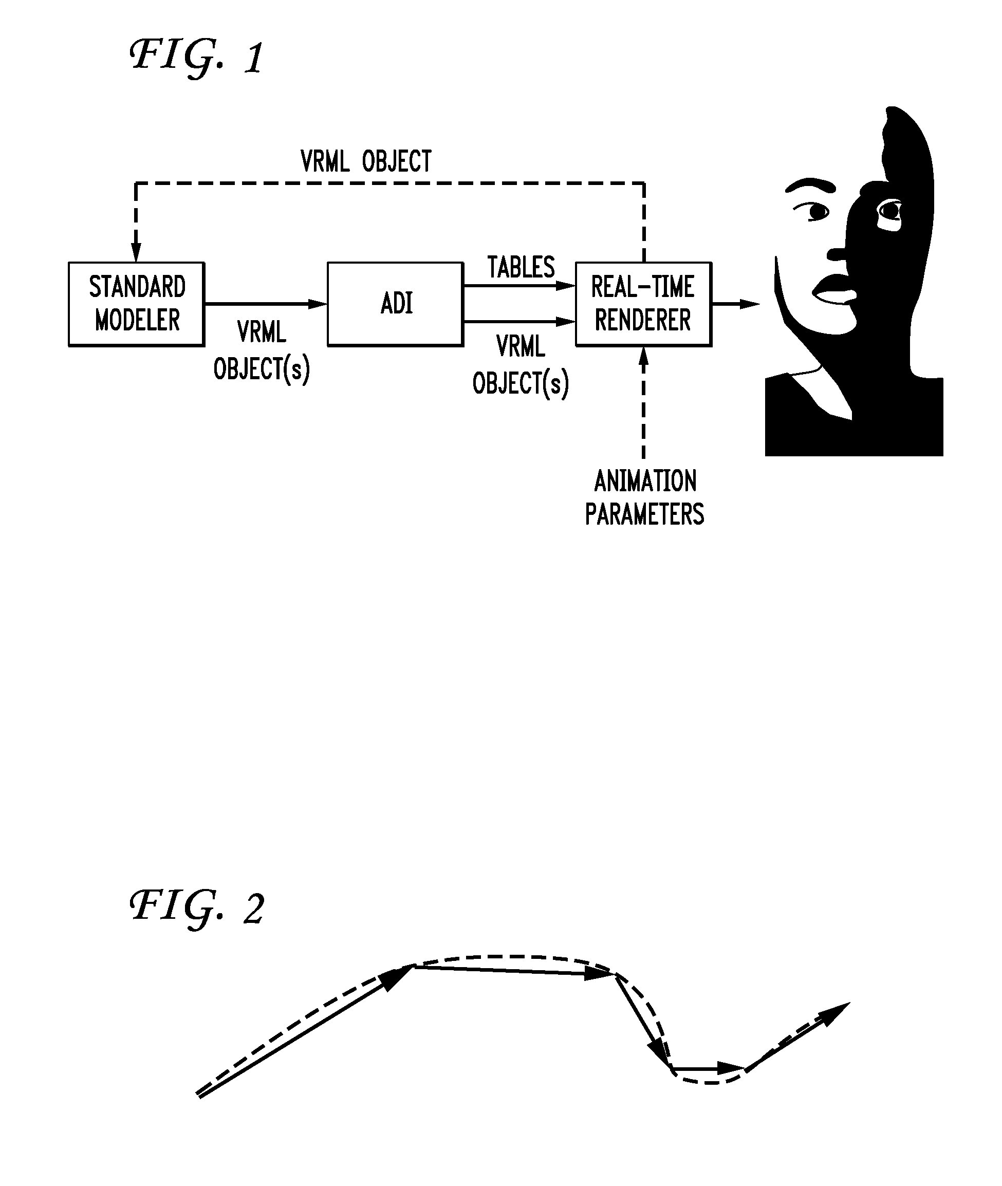
[0012]Another object of the present invention is to provide an animation definition interface for an MPEG renderer which can be easily and inexpensively implemented allowing for animation of arbitrary downloaded models in the MPEG-4 terminal.
[0013]It is another object of the present invention to provide an inexpensive and easily followed method for real-time animation.
[0015]In a second aspect of the invention, a system is provided for defining a set of computer animation parameters for an object to be animated electronically. The animation is achieved by electronically altering at least a portion of the object in a controlled manner. Example computer hardware, as would be known to one of skill in the art, includes a hard drive storing a computer program that may be loaded into computer memory and run by a central processing unit to carry out the various functions directed by the computer program. The system includes means for obtaining an electronic reference model of the object to be animated, means for altering the electronic reference model to form a modified model corresponding to a first animation parameter, means for determining the physical differences between the electronic reference model and the modified model and storing the differences as the first animation parameter, means for repeating the altering and the determining for each of the animation parameters to be defined, means for providing the stored parameters to a rendering device for generation of the animation in accordance with the stored parameters, means for storing the animation parameters as a lookup function in a table, and means for including the definition of an object as a scenegraph and the definition of high level animation parameters to allow rigid and flexible deformation.

Problems solved by technology

Usually, animation of a proprietary model is not compatible with MPEG-4 requirements.
Furthermore, the current implementation and modification of animation parameters, like smiles or eyebrow movement, with these renderers is cumbersome and time consuming.

Method used


Image

  • Method for defining animation parameters for an animation definition interface
  • Method for defining animation parameters for an animation definition interface
  • Method for defining animation parameters for an animation definition interface

Examples


Embodiment Construction

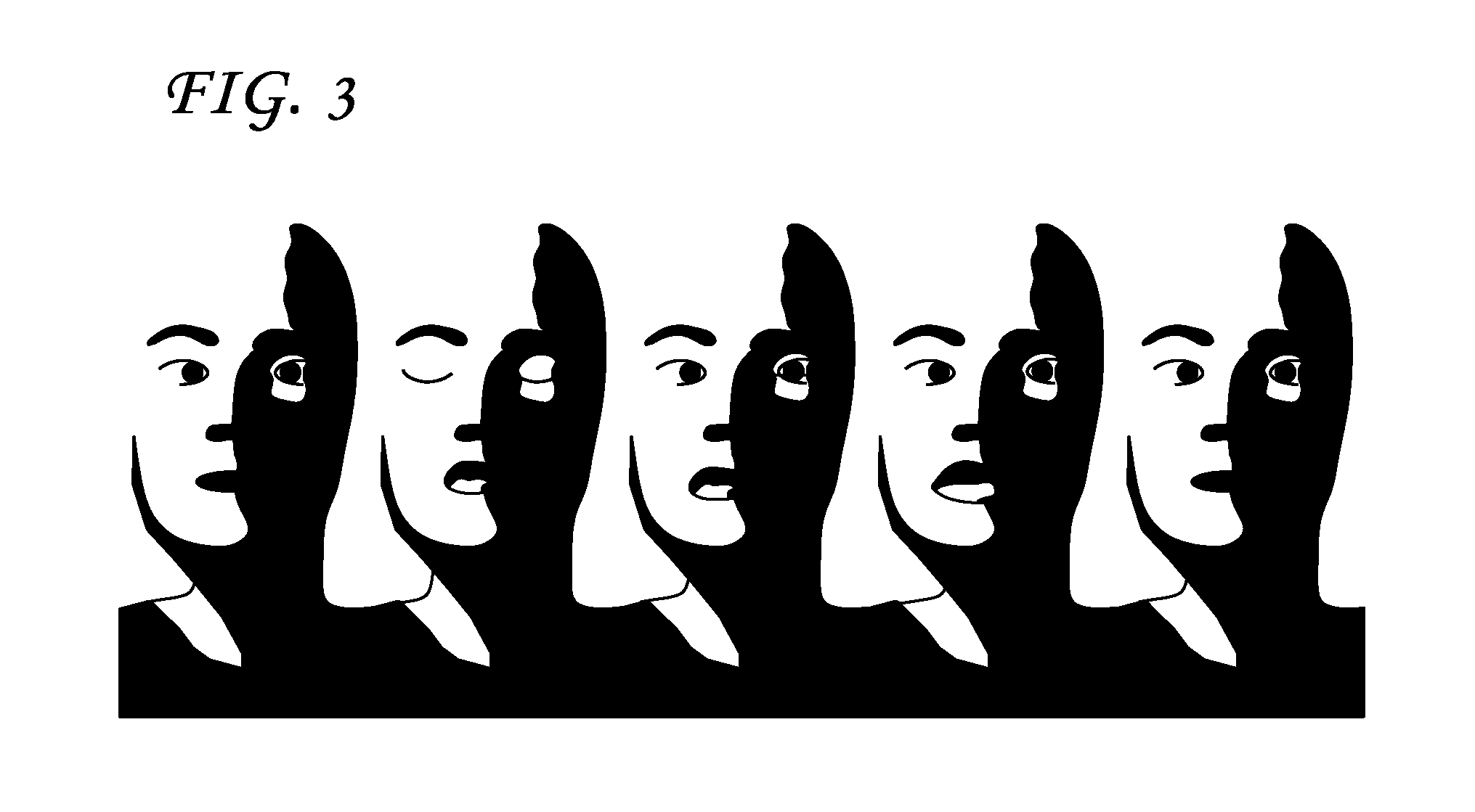
[0020]The MPEG-4 standard described above strives to define a standardized interface to allow animation of face and body models within an MPEG-4 terminal. Due to the rapid advances in computer graphics hardware, it is not foreseen that MPEG-4 will standardize face and body models. Instead, face and body definition parameters (“FDP”, “BDP”) are defined for specifying the shape and surface of a model. For the animation of the models, face and body animation parameters (“FAP”, “BAP”) are standardized.

[0021]These animation parameters include low-level parameters like “move left eyebrow up” and “tongue roll” as well as high-level parameters like “smile”. Assuming that different terminals allow for models with different degrees of complexity, a process is required that allows the rapid development of models suited for animation. The use of standardized file format like Virtual Reality Modeling Language (“VRML”) allow the use of commonly available modeling software (modelers), like COSMO 3...


PUM


Abstract

A system and a computer-readable medium are provided for controlling a computing device to define a set of computer animation parameters for an object to be animated electronically. An electronic reference model of the object to be animated is obtained. The reference model is altered to form a modified model corresponding to a first animation parameter. Physical differences between the electronic reference model and the modified model are determined and a representation of the physical differences are stored as the first animation parameter. Altering of the reference model and determining of the physical differences are repeated. The stored parameters are provided to a rendering device for generation of the animation in accordance with the stored parameters. Determining physical differences between the electronic reference model and the modified model and storing a representation of the physical differences as the first animation parameter include comparing vertex positions of the reference model.

Description

[0001]This application is a continuation of U.S. patent application Ser. No. 11 / 179,715, filed Jul. 12, 2005, which is a continuation of U.S. patent application Ser. No. 10 / 291,428, filed on Nov. 12, 2002, now U.S. Pat. No. 6,970,172, which is a continuation of U.S. patent application Ser. No. 09 / 975,052, filed Oct. 12, 2001 and now abandoned, which is a continuation of U.S. patent application Ser. No. 09 / 031,728, filed on Feb. 27, 1998, now U.S. Pat. No. 6,154,222, issued on Nov. 28, 2000, which claims the benefit of U.S. Provisional Patent Application No. 60 / 041,732, filed on Mar. 27, 1997. The contents of the above U.S. Patents and provisional and non-provisional U.S. Patent Applications are herein incorporated by reference in their entirety.[0002]The present invention generally relates to the field of computer animation and more particularly, is directed to a method for defining animation parameters for an animation definition interface.BACKGROUND OF THE INVENTION[0003]In recent...

Claims


Application Information

Patent Timeline
Patent Type & Authority Patents(United States)
IPC IPC(8): G06T15/00G06T9/00G06T15/70
CPCG06T9/001G06T13/40G06T2213/04G06T2210/61
Inventor HARATSCH, ERICHOSTERMANN, JOERN
Owner AT&T INTPROP II L P
Learn More