Automatic gain control technique for current monitoring in current-mode switching regulators

a current-mode switching regulator and automatic gain control technology, applied in the direction of power conversion systems, dc-dc conversion, instruments, etc., can solve the problems of reducing power efficiency, difficult to implement third technique, and inability to achieve second techniqu

Inactive Publication Date: 2011-04-05
MICROSEMI
View PDF40 Cites 204 Cited by
  • Summary
  • Abstract
  • Description
  • Claims
  • Application Information

AI Technical Summary

Benefits of technology

For purposes of summarizing the invention, certain aspects, advantages and novel features of the invention have been described herein. It is to be understood that not necessarily all such advantages may be achieved in accordance with any particular embodiment of the invention. Thus, the invention may be embodied or carried out in a manner that achieves or optimizes one advantage or group of advantages as taught herein without necessarily achieving other advantages as maybe taught or suggested herein.

Problems solved by technology

A design challenge for the current-mode switching regulator is how to reliably monitor the inductor current.
This common technique decreases power efficiency because of additional conversion loss due to the small sense resistor.
The second technique is not possible when the switch and the current-mirror circuit are not parts of a common integrated circuit.
The third technique is difficult to implement because the inductor's DC resistance needs to be reliably constant and known apriori.
The main disadvantage of the fourth technique is that the switch's on-resistance typically varies significantly depending on manufacturing variation, temperature variation, and switch control variation.

Method used


Image

  • Automatic gain control technique for current monitoring in current-mode switching regulators
  • Automatic gain control technique for current monitoring in current-mode switching regulators
  • Automatic gain control technique for current monitoring in current-mode switching regulators

Examples


Embodiment Construction

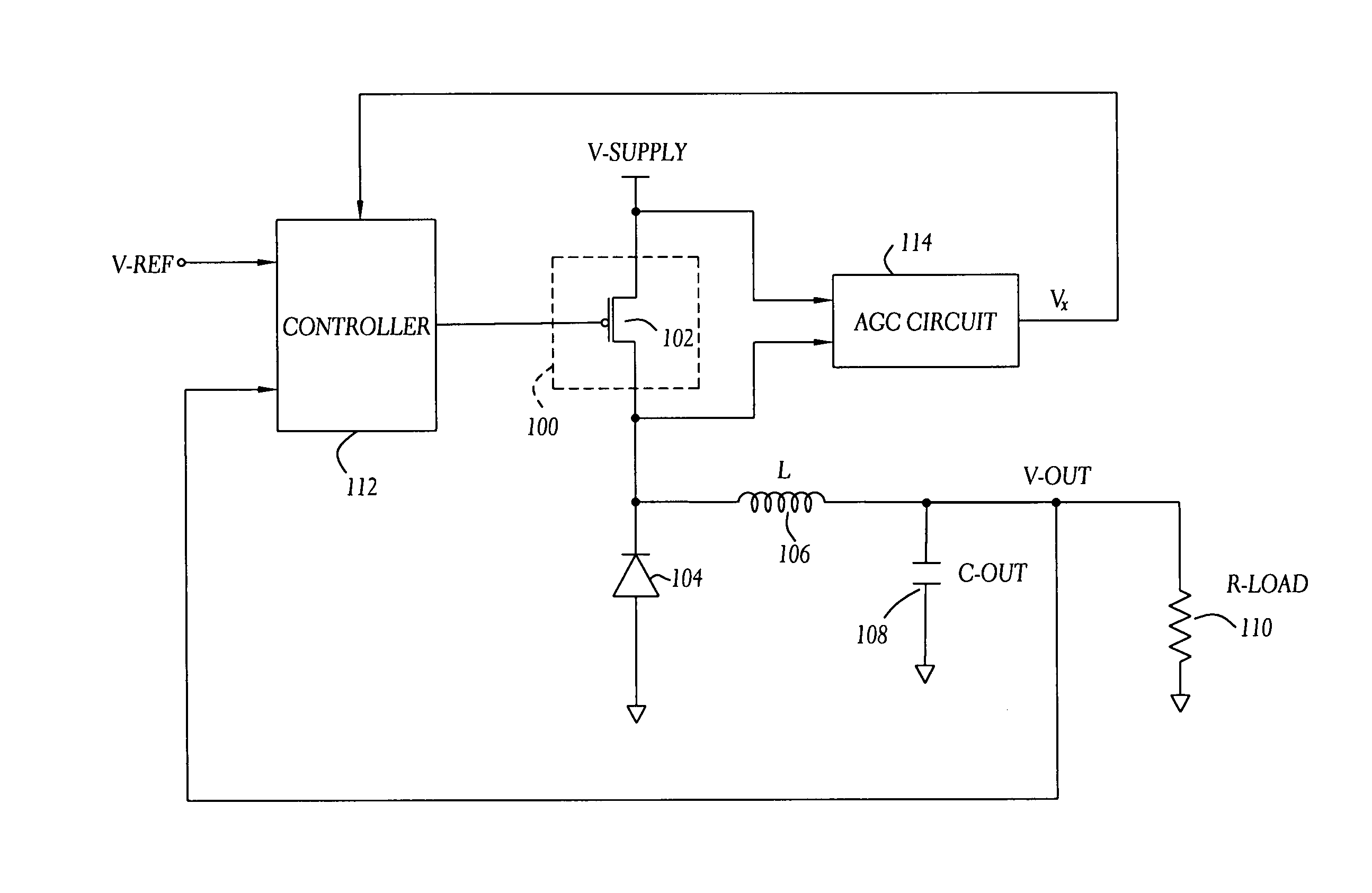
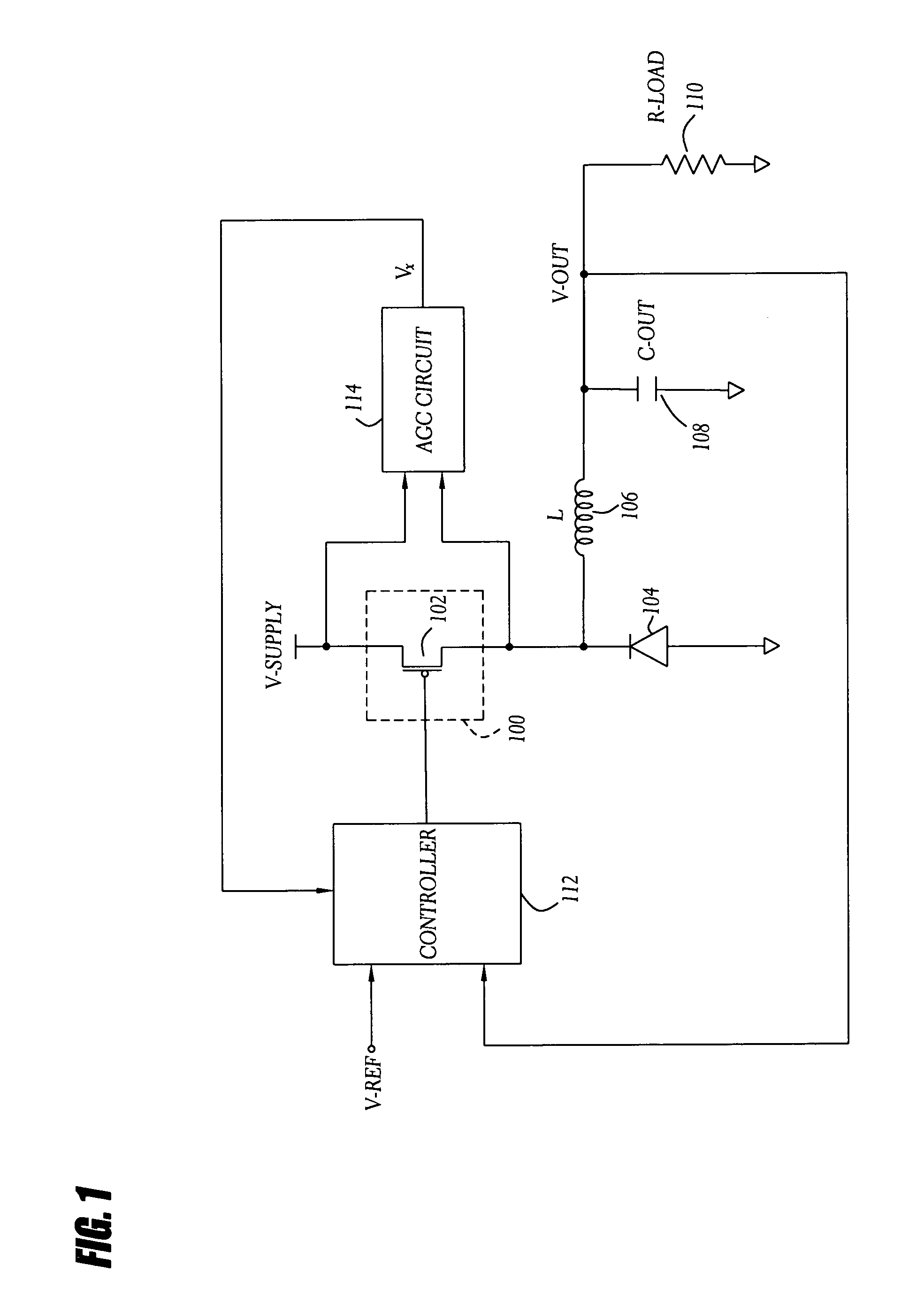
Embodiments of the present invention will be described hereinafter with reference to the drawings. FIG. 1 is a block diagram of one embodiment of a current-mode buck converter using adaptive current sensing (or an automatic gain control technique for current monitoring). The current-mode buck converter accepts a DC source voltage (V-SUPPLY) of one level (e.g., power from a battery) and produces a DC output voltage (V-OUT) of another, and typically lower, level. A first semiconductor switch (or high-side switch) 100 is coupled between the DC source voltage (or supply voltage) and a first terminal of an inductor (L) 106. A second terminal of the inductor 106 is coupled to the DC output voltage. An output capacitor (C-OUT) 108 and an output resistor (R-LOAD) 110 are coupled to the DC output voltage to represent a load (e.g., a microprocessor). The output capacitor 108 can also represent filter capacitance used to reduce ripple in the DC output voltage. A diode 104 (or alternately a sec...


PUM


Abstract

A current-mode switching regulator uses adaptive current sensing to reliably monitor an inductor current in a cost-efficient and power-efficient manner. A semiconductor switch periodically turns on to conduct the inductor current. A voltage drop across the semiconductor switch is monitored when the semiconductor switch is on. A variable gain amplifier with an automatic gain control loop generates a feedback signal from the voltage drop of the semiconductor switch when conducting to provide an indication of the inductor current to a controller. The automatic gain control loop compensates for any variations in the on-resistance of the semiconductor switch.

Description

BACKGROUND OF THE INVENTION1. Field of the InventionThe present invention relates generally to a power conversion circuit and more particularly to current monitoring in switching regulators.2. Description of the Related ArtA power conversion circuit (e.g., a switching regulator) accepts a Direct Current (DC) voltage source at one level and outputs a desired DC voltage at another level. The switching regulator includes one or more semiconductor switches. The switches alternate between connecting and disconnecting the voltage source to circuits that drive the output. The output voltage level is related to the duty cycle of the switching. The switching is typically controlled by a Pulse-Width Modulation (PWM) circuit.A switching regulator (or switched mode power supply) can be configured for voltage-mode operation or current-mode operation. In voltage-mode operation, an output voltage of the switching regulator is monitored to adjust switching duty cycle. In current-mode operation, the...

Claims


Application Information

Patent Timeline
Patent Type & Authority Patents(United States)
IPC IPC(8): G05F1/652G05F3/16
CPCH02M3/156H02M2001/0009H02M1/0009
Inventor FAHRENBRUCH, SHAWN ANTHONY
Owner MICROSEMI
Why Eureka
Try Eureka