Display device
a display device and display technology, applied in static indicating devices, instruments, non-linear optics, etc., can solve the problem of not being able to optimize white balance by this method, and achieve the effect of effectively suppressing white optimizing white balance in the reflective display, and increasing the proportion of the reflective region in the blue filter having a high color temperatur
- Summary
- Abstract
- Description
- Claims
- Application Information
AI Technical Summary
Benefits of technology
Problems solved by technology
Method used
Image


Examples
embodiment 1
(1-1) Embodiment 1
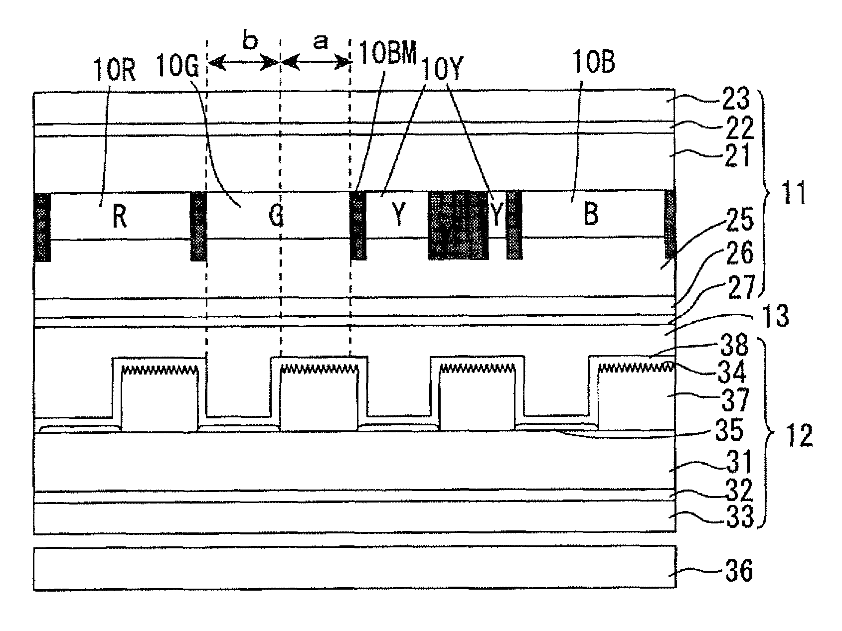
[0089]FIG. 6 is a planar view schematically showing a configuration of a TFT substrate 12 in a transflective display device in accordance with Embodiment 1 of the present invention.
[0090]As the TFT substrate 12 in the present Embodiment, as shown in FIG. 6, a matrix wiring consisting of a gate bus line 5 and a source bus line 6 is arranged on a glass substrate 31. A transmissive electrode 35 and a reflective electrode 34 are arranged in the region surrounded by the matrix wiring. These electrodes face the respective filters having different colors which are arranged in a below-mentioned color filter substrate 11. Further, these electrodes are connected to a drain electrode of a thin film transistor (TFT, not shown) arranged below the reflective electrode 34. In the region below the reflective electrode 34, a storage capacitance (Cs) wiring 7 is arranged in parallel to the gate bus line 5 to maintain a voltage applied to the transmissive electrode 35 and the reflect...
embodiment 2
(1-2) Embodiment 2
[0109]FIG. 12 is a planar view schematically showing a configuration of one pixel in a liquid crystal display device in accordance with Embodiment 2 of the present invention.
[0110]According to the pixels in the present Embodiment, as shown in FIG. 12 and the above-mentioned Table 1, the transmissive region Yb in the yellow filter 10Y is extended, thereby decreasing the proportion of the area of the reflective region Ya in the yellow filter 10Y by 0.23 relative to the standard area proportion, similarly in Embodiment 1. The proportion of the area of the transmissive region Yb in the yellow filter 10Y is set to be larger than the standard transmissive area proportion by 0.23.
embodiment 3
(1-3) Embodiment 3
[0111]FIG. 13 is a planar view schematically showing a configuration of one pixel in the liquid crystal display device in accordance with Embodiment 3 of the present invention.
[0112]According to the pixels in the present Embodiment, as shown in FIG. 13 and the above-mentioned Table 1, the region which is shielded by the black matrix 10BM is extended, thereby decreasing the proportion of the area of the reflective region Ya in the yellow filter 10Y by 0.10 relative to the standard area proportion. Further, the transmissive region Bb in the blue filter 10B is decreased, thereby increasing the proportion of the area of the reflective region Ba in the blue filter by 0.10 relative to the standard area proportion.
PUM
| Property | Measurement | Unit |
|---|---|---|
| color temperature | aaaaa | aaaaa |
| visible wavelength | aaaaa | aaaaa |
| luminous reflectance | aaaaa | aaaaa |
Abstract
Description
Claims
Application Information
 - R&D
- Intellectual Property
- Life Sciences
- Materials
- Tech Scout
- Unparalleled Data Quality
- Higher Quality Content
- 60% Fewer Hallucinations
Browse by: Latest US Patents, China's latest patents, Technical Efficacy Thesaurus, Application Domain, Technology Topic, Popular Technical Reports.
© 2025 PatSnap. All rights reserved.Legal|Privacy policy|Modern Slavery Act Transparency Statement|Sitemap|About US| Contact US: help@patsnap.com