
Vanes for exposure to vibratory loading

a technology of vibratory loading and vanes, which is applied in the direction of computer aided design, special data processing applications, liquid fuel engine components, etc., can solve the problems of blade failure, unsteady aerodynamic forces, and typical high frequency vibration of vanes

Inactive Publication Date: 2011-03-22
ROLLS ROYCE PLC
View PDF1 Cites 11 Cited by
  • Summary
  • Abstract
  • Description
  • Claims
  • Application Information

AI Technical Summary

Benefits of technology

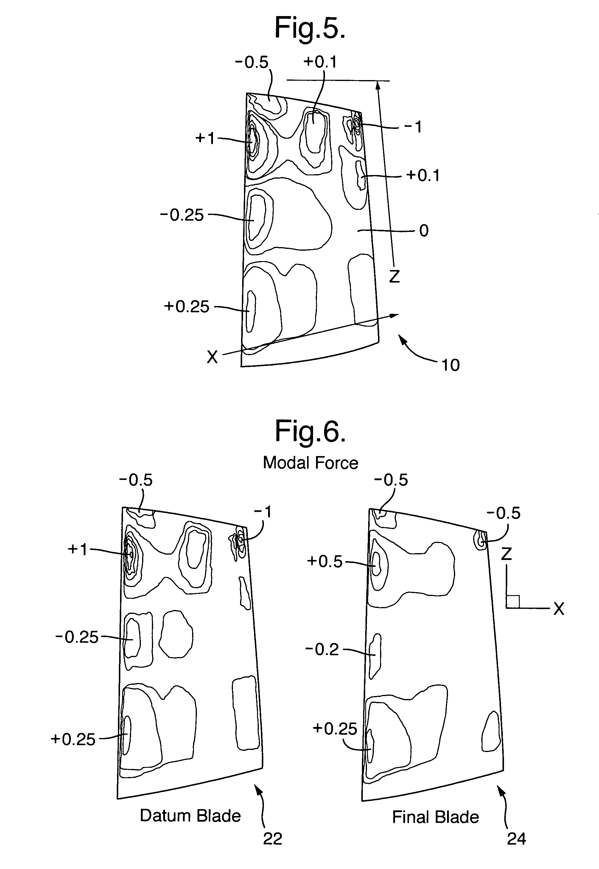
[0017]In particular, it is preferred to minimise the correlation between (a) and (b). The varying force (a) may be considered to have a shape (sometimes referred to as a “pressure shape”). The vibrational mode (b) may be considered to have a displacement characteristic or modeshape. Preferably the matching between the modeshape and pressure shape is minimised.
[0041]Alternatively, the area-cumulative quantitative characteristic may be determined by summing quantitative characteristics determined for local vane elements located on the area of interest of the vane. Preferably, the local vane elements are contiguous. This step may be useful in particular if the area of interest is not a straight-sided or regular shape. Use of this step avoids the need to determine first the line-cumulative data before determining the area-cumulative data.
[0047]Preferably, the area-cumulative (or surface-cumulative) quantitative characteristic is a scalar quantity. In this way, an area-cumulative quantitative characteristic for the first design may be compared in a straightforward manner with an area-cumulative quantitative characteristic for the second design. Similarly, the line-cumulative quantitative characteristic is a scalar quantity. Therefore, the line-cumulative quantitative characteristics for the first design may be compared in a straightforward manner with the line-cumulative quantitative characteristics for the second design. These comparisons can give important information about the likely forced response levels of the vane of the first design, and important information about the likely improvement brought about by the change of design to give the second design.

Problems solved by technology

When subjected to high speed airflows, vanes typically become susceptible to large amplitude vibration, often caused by unsteady aerodynamic forces.
The unsteady aerodynamic forces are caused by the “wakes” of components upstream in the fluid-conveying duct.
Such vibrations are detrimental to the compressor blade, and may result in failure of the blade.
However, this is difficult to implement in practice without altering the performance (i.e. efficiency) of the engine or turbomachinery.
However, this increases the axial length of the engine / machinery and thus increases the total weight.
This is undesirable.
However, this is difficult to introduce and control.

Method used


Image

  • Vanes for exposure to vibratory loading
  • Vanes for exposure to vibratory loading
  • Vanes for exposure to vibratory loading

Examples


Embodiment Construction

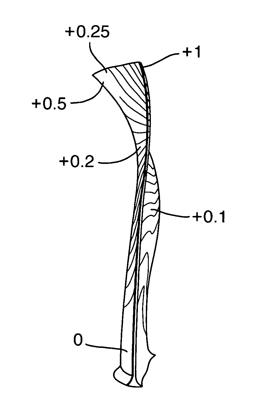
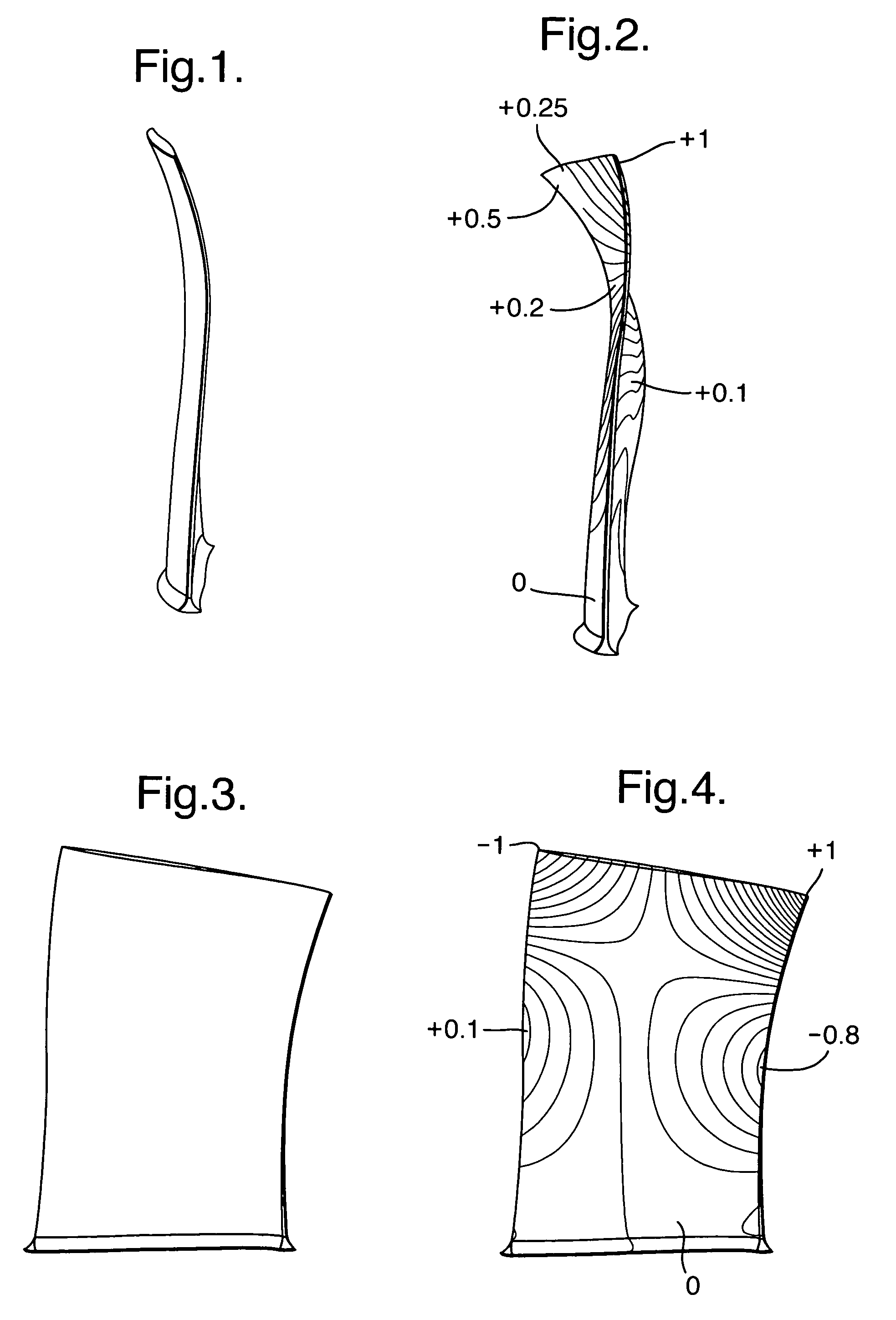
[0077]The following embodiments will be described with reference to a blade, in particular to a compressor blade of an aero engine. One such blade is shown schematically in FIGS. 1 and 2.

[0078]FIG. 1 shows a drawing of a blade in a non-deformed state. This shape is assumed by this blade when no steady state or vibrational load is applied to the blade. FIG. 2 shows a drawing of the same blade as FIG. 1. However, FIG. 2 shows an instantaneous shape of the blade which is different to that of FIG. 1. In FIG. 2, the blade is deformed due to a vibrational load. A measure of deformation of local elements of the blade is given by the displacement of each local element with respect to the position of the same local element in its non-deformed state. In FIG. 2, the shaded contours indicate lines of equal displacement. The values shown are normalised between 0 and 1. It can be seen that one corner tip of the blade has a significantly higher normalised displacement than the remainder of the bla...


PUM


Abstract

Disclosed are methods for designing vanes that, in use, are expected to be exposed to vibratory loading, in particular rotor or stator vanes for aero engines or turbomachinery. A quantitative characteristic (modeshape) is used which is a measure of correlation between the excitation force to which the vane is to be subjected in use and a vibrational mode of the vane, corresponding to a characteristic frequency of the excitation. The modeshape of the first design is determined. Then the first design is modified to give a second design, by one or more of leaning, sweeping or twisting the blade design, or by altering the local shape of the design, or by altering the material of the design. Then the modeshape of the second design is determined. The design modification gives rise to a reduction in the forced response levels.

Description

TITLE OF THE INVENTIONCROSS-REFERENCE TO RELATED APPLICATIONS[0001]This application is a continuation of U.S. application Ser. No. 10 / 962,470, filed Oct. 13, 2004, now abandoned, which claims priority to Great Britain patent application No. GB 0325215.2, filed Oct. 29, 2003.BACKGROUND OF THE INVENTION[0002]The present invention relates to methods and systems for designing components that, in use, are expected to encounter vibratory loading. In particular, the invention has applicability in the field of aero engines and turbomachinery.[0003]A typical turbine engine (or typical turbomachinery) contains several annular fluid-conveying ducts which form, e.g., the compressor or turbine sections of the engine.[0004]Each of these ducts contains a number of blades or vanes (which are henceforth called guide vanes or simply vanes) circumferentially distributed in one or more vane assemblies in the duct. The vanes are categorized as rotor blades or stator vanes depending on whether or not the...

Claims


Application Information

Patent Timeline
IPC IPC(8): F03B3/12F01D5/16
CPCF01D5/141F01D5/16F04D27/001F04D29/324F05D2250/31G06F17/5009G06F2217/16Y10S416/02G06F30/20G06F2111/10
Inventor SIMPSON, GEORGEPENG, CAETANOMAY, GORDONVAHDATI, MEHDISAYMA, ABDULNASERIMREGUN, MEHMET
Owner ROLLS ROYCE PLC
Learn More