
Implantable pump with reservoir level detector

a technology of reservoir level and pump, which is applied in the direction of intravenous devices, medical preparations, other medical devices, etc., can solve the problem that the measured inductance is not varied enough to provide accurate measurements

Inactive Publication Date: 2011-03-15
MEDOS INT SARL
View PDF21 Cites 11 Cited by
  • Summary
  • Abstract
  • Description
  • Claims
  • Application Information

AI Technical Summary

Benefits of technology

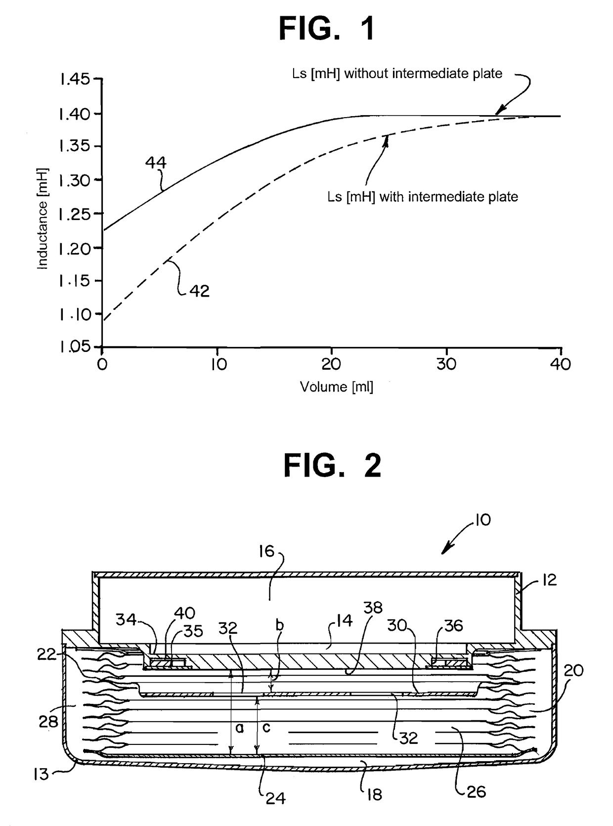
The use of an intermediate plate provides accurate fluid volume measurements across the entire reservoir range, including above 20 ml, with ±5 ml accuracy between 20-40 ml and ±2 ml accuracy between 0-20 ml, and enables detection of pump malfunctions like leaks or blockages.

Problems solved by technology

At fluid levels greater than about 20 ml and because of the increasing distance between the coil and the bottom plate at those greater volumes, the measured inductance doesn't vary enough to provide accurate measurements.

Method used


Image

  • Implantable pump with reservoir level detector
  • Implantable pump with reservoir level detector

Examples


Embodiment Construction

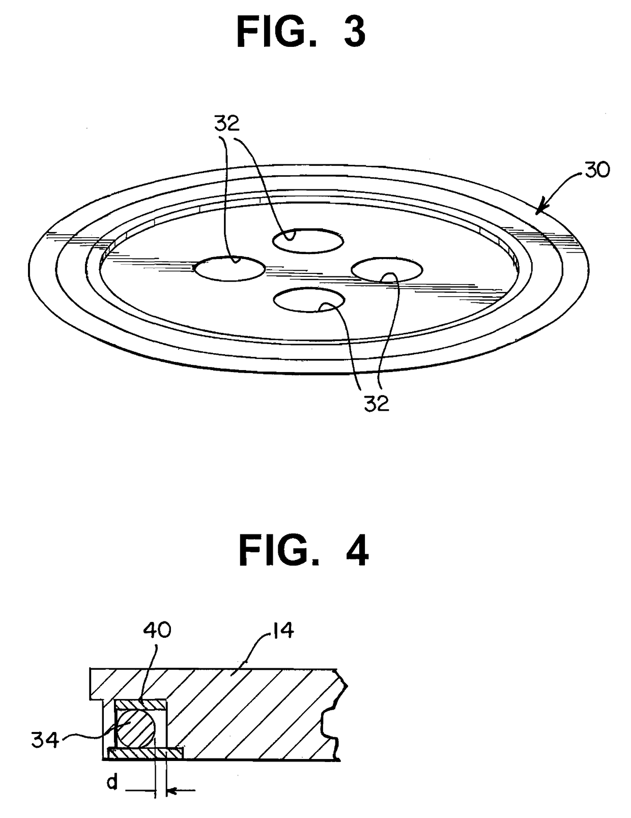
[0013]Referring now to FIGS. 1-4, an implantable pump 10 in accordance with the present invention is illustrated. Pump 10 has a housing 12. The housing is comprised of a base plate 14 and a can 13. Can 13 is attached to the base plate 14. Base plate bottom 14 divides the housing into an electronics chamber 16 and a propellant chamber 18. A bellow mechanism 20 is connected to the base plate 14 and is disposed within the propellant chamber 18. The bellow mechanism 20 has an expandable sidewall 22 and a bottom plate 24. The bellow mechanism 20 divides the propellant chamber into a medicament-receiving portion 26 and a non-medicament receiving portion 28. In a currently preferred exemplary embodiment, portion 28 is a propellant receiving portion 28 so that a force is applied to the bellows causing the medicament within medicament-receiving portion 26 to be delivered to an outlet of pump 10 in a manner known to those skilled in the art. Alternatively, the pump maybe an active pump, such ...


PUM


Abstract

An implantable pump includes a base plate and a can that are parts of the pump housing. The base plate bottom divides the housing into a first electronics chamber and a second chamber. A bellows mechanism is connected to the base plate and is disposed within the second chamber. The bellow mechanism has an expandable sidewall and a bottom plate. The bellow mechanism divides the second chamber into a medicament receiving portion and a non-medicament-receiving portion. The bellow mechanism has an intermediate plate disposed within the medicament-receiving portion. A coil is disposed in a recess on the lower surface of the base plate, and the coil is spaced from an internal wall of the recess. The amount of fluid remaining in the implantable pump can be monitored by energizing the coil. A primary magnetic field is generated by the energized coil. A secondary magnetic field, which is dependant on the position of the bottom and intermediate plate of the bellow mechanism, couples back to the primary field affecting the electrical characteristics of the coil. The amount of fluid remaining in the reservoir is determined based on the resulting changes in the electrical characteristics of the coil.

Description

CROSS-REFERENCE TO RELATED APPLICATIONS[0001]Not applicable.STATEMENT REGARDING FEDERALLY SPONSORED RESEARCH[0002]Not Applicable.FIELD OF THE INVENTION[0003]The present invention relates to an implantable infusion pump having a reservoir level detector. More specifically, the present invention relates to an implantable infusion pump having a reservoir with an intermediate plate, which can be used to indicate the amount of fluid remaining within the reservoir.BACKGROUND OF THE INVENTION[0004]U.S. Pat. No. 6,755,814, which is commonly owned by the assignee of the present invention, discloses an implantable infusion pump that has a reservoir level detector. The pump includes a housing having a can and a base plate, which base plate bottom divides the housing into a pump electronic chamber and a propellant chamber. A bellow mechanism is disposed within the propellant chamber. The bellow mechanism has a base or bottom plate. The medicament for delivery to a patient is stored within the b...

Claims


Application Information

Patent Timeline
Patent Type & Authority Patents(United States)
IPC IPC(8): A61M37/00A61K9/22
CPCA61M5/14276A61M5/1684A61M2205/3389A61M2205/3317
Inventor UTARD, THIERRYPETITHORY, JEAN-SEBASTIENMARGAIRAZ, PHILIPPECRIVELLI, ROCCOGINGGEN, ALEC
Owner MEDOS INT SARL
Learn More