
Dispensing closure with a plug-through sleeve for fixing it to a container

a technology of container and plug-through sleeve, which is applied in the field of container, can solve the problems of high interference for the appropriate use of the solution, the production of known container solutions can be regarded at least in some degree as complicated, and the cost of production is high, so as to facilitate production and improve the effect of practical handling

Inactive Publication Date: 2011-03-15
HANSEN BERND
View PDF12 Cites 5 Cited by
  • Summary
  • Abstract
  • Description
  • Claims
  • Application Information

AI Technical Summary

Benefits of technology

[0004]An object of the present invention is to provide an improved container with better practical handling with simultaneously facilitated production.
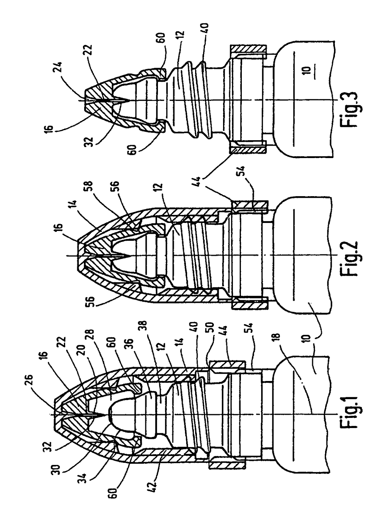
[0007]As a result of the respective plausible application arrangement for the two application solutions, incorrect application is largely precluded. Even if the container solution according to the present invention optionally has more functional components, especially in the form of two cap parts, than the known solutions, the second cap part being an integral component of the first cap part and being overlapped by the latter in the uncleared positions for the opening, the container according to the present invention overall can be easily and economically produced. The container body can be produced especially within the framework of a blow-fill-seal process, as has become known in the trade under the trademark “Bottelpack®”. The cap parts are produced preferably in an injection molding process.
[0008]In one especially preferred embodiment of the container according to the present invention, driver elements of the first cap part which act on the second cap part induce an entraining motion. After the second cap part on the neck part engages, the fixing part is interlocked in the other direction of action and releases the first cap part as it is being unscrewed. This operation ensures reliable use. The axial distance of travel of the cap parts relative to one another are in any case dimensioned such that reliable locking of the second cap part to the container body takes place. The first cap part can then clear the container opening without hindrance. By preference, to interlock the second cap part on the neck part of the container body, it has an engagement region tapering by one step to the inside and being engaged by at least one engagement part, preferably in the form of an engagement clip, of the second cap part, after crossing the step.
[0009]In another especially preferred embodiment of the container according to the present invention, the first cap part has a fixing part which in one direction of action enables the process of screwing on the first cap part and in the other direction of action remains on the container and releases the first cap part for an unscrewing process so that in this way a further defined connection to the parts of the container body is formed by the fixing part. This arrangement helps prevent the penetration of foreign media. The fixing part allows the operator reliable use of the cap part arrangement.
[0010]In this connection, it is preferable that the fixing part is a ring-shaped fixing body having an elastic catch projecting to the inside and extending in one direction of action over the corresponding catch on the container and interlocking with them in the other direction of action. Preferably, the first cap part on its free side facing the container body has a fixing part and is connected to the fixing part via an easily detachable separation site. In this way, in the process of clearing the container opening via the first cap part, the ring-shaped fixing part remains on the container body and the first cap part can be separated from the fixing part with low actuating forces.

Problems solved by technology

These situations may result in the liquid emerging at several locations in a direction deviating from the longitudinal axis and present a high degree of interference for the appropriate use of the solution.
The production of the known container solutions can be regarded at least to some extent as complicated, and therefore, costly.

Method used


Image

  • Dispensing closure with a plug-through sleeve for fixing it to a container
  • Dispensing closure with a plug-through sleeve for fixing it to a container

Examples


Embodiment Construction

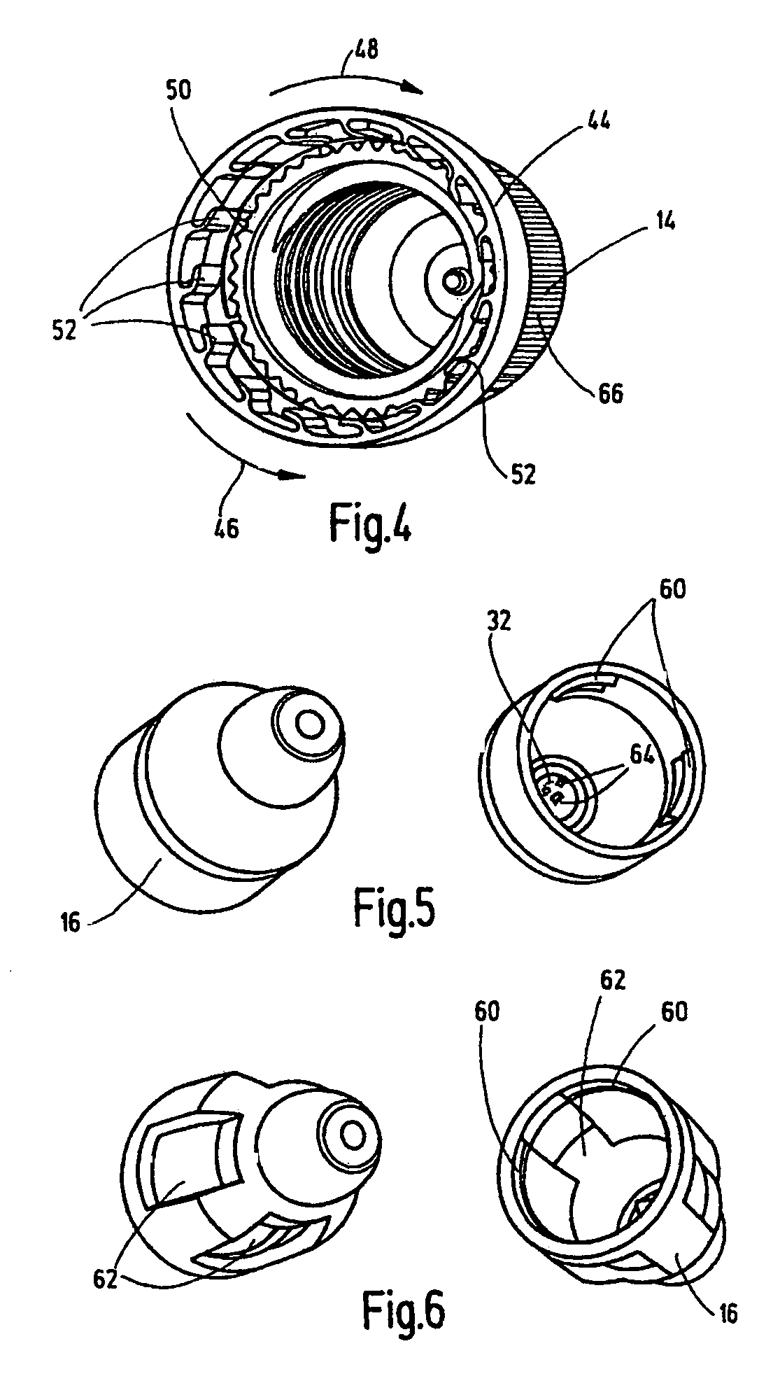
[0018]The container shown in FIG. 1 in its upper region is produced especially in a blow molding process and placed in the mold and sealed. In particular, the container made in the form of an ampule is produced from plastic material. The opening device shown below is also usable for container solutions produced differently. The container body 10 is followed to the top by the neck part 12 onto which the first cap part 14 can be screwed or threaded. This cap part 14 is shown in FIG. 4 in a perspective bottom view. The container body 10 can store a fluid which will not be detailed, for example, in the form of a medicinally acting liquid in the form of eye drops or the like. Instead of liquids, also pasty or gaseous active substances can be placed in the container body, for example, with the blow molding process known in the trade under the trade name “Bottelpack®”.

[0019]In addition to the first cap part 14, a second cap part 16 extends in the axial longitudinal direction 18 of the cont...


PUM


Abstract

A container, in particular a plastic ampule produced using a blow-molding process and filled and closed in the mold has a neck part (12) adjoining a container body (10) and threadly receiving a first cap part (14). A second cap part (16) extends at least partly between the first cap part (14) and the neck part (12) and is provided with an opening device (20). The opening device has at least one opening (22) for opening the container body (10), and can be closed by the first cap part (14). The first cap part (14) carries the second cap part (16) by the screwing-on process of the first cap part in such a way that the opening device (20) causes the container body (10) to be opened. A closure part (closure pin 26) of the first cap part (14) unblocks the opening (22) in the opening device (20) after the first cap part is unscrewed, with the second cap part (16) remaining on the neck part (12).

Description

FIELD OF THE INVENTION[0001]The present invention relates to a container, in particular a plastic ampule, having a neck part adjoining the container body and threadly receiving a first cap. A second cap part extends at least partially between the first cap part and the neck part and is provided with an opening device having at least one opening for opening the container body. The container body can be closed by the first cap part.BACKGROUND OF THE INVENTION[0002]DE 42 32 305 C1 discloses a cap for containers, especially bottles produced from plastic in a blow molding process and filled and sealed in the mold, also in ampule form. A neck on the container receives a cap. The neck is made integrally with a dropper. That patent specification describes as known solutions bottles of this type, with an externally threaded neck being closed on a free end by a closure part made integrally with the neck. A cap screwed onto the neck is provided inside with a centrally arranged mandrel to punct...

Claims


Application Information

Patent Timeline
Patent Type & Authority Patents(United States)
IPC IPC(8): B65D51/20B65D41/00B65D17/44B65D41/36B65D17/42B65D39/00
CPCB65D51/226B65D2251/0015B65D2251/0096B65D51/22
Inventor HANSEN, BERND
Owner HANSEN BERND
Learn More