
Interlocking mortarless structural concrete block building system

a technology of interlocking mortar and structural concrete, which is applied in the direction of walls, constructions, building components, etc., can solve the problems of inability to communicate horizontally, the final product is usually heavy and rough in texture, and the actual performance of the core is marginal, so as to achieve enhanced performance, improve efficiency, and improve the effect of construction efficiency

Active Publication Date: 2011-03-15
AUGUST JOHN
View PDF28 Cites 17 Cited by
  • Summary
  • Abstract
  • Description
  • Claims
  • Application Information

AI Technical Summary

Benefits of technology

[0016]The disclosed embodiments of the present invention provide a mortarless, open-celled cavity concrete wall building block system, which when grouted with concrete, interlocks all individual block units into a singular monolithic concrete mass. The disclosed embodiments provide greater efficiency, not only in functional mass, but also speed of installation. It can be utilized by semi-skilled labor. Performance is enhanced from an engineering standpoint as demonstrated when assembled in a structural configuration. The created integral spaces together function as a single monolithic open cavity for solid concrete grout fill both laterally and vertically. It is designed to be simpler, swifter, and stronger than other block systems, whether they be of concrete or plastic.
[0018]a) A simple system of four basic parts, which upon assembly using a plurality of shapes and forms, any number of practical structural configurations can be constructed easily by semi skilled labor.
[0023]f) Blocks that can be set without mortar, but instead glued in place with any number of construction adhesives such as epoxy formulated for concrete. The purpose of this aspect is to supply enough transverse shear to offset the hydrostatic pressure of wet concrete and prevent accidental displacement before grouting. It may or not be a structural bond, as it is the grout itself which interlocks the block.
[0033]Further advantages include a new modulus size based on a standard other than the common brick which can either be English or Metric equivalent and be approximately the same in measurement and standardization, thus creating a more universally versatile and easier handled cmu. Another improvement is a cmu having a smoother surface, which makes it both easier to handle and to enhance the application of subsequent coatings, such as paint. Another aspect is creation of more user friendly cmus, which extends construction parameters to those with no specific prior skills.

Problems solved by technology

The final product is usually heavy and rough in texture.
While most concrete block usually have vertical cellular cores, the majority of these cores are non-communicative horizontally.
From a production standpoint, the manufacture of these types of blocks is economical; however, their actual performance is marginal.
a) Common to most concrete blocks is a size and weight that makes placement cumbersome. The functional elements are limited by a dense concrete shell, which severely restricts communication from core to core and which adds unnecessary weight while serving marginal functionality.
b) The majority of these cells are usually vertical, although some cells have provision for horizontal channels. There is little horizontal cohesion in a wall of this nature except what is achieved by lateral reinforcement bars.
c) Between each block is laid a horizontal bed of mortar, the bed joint, and a vertical line of mortar, the head joint. The blocks essentially remain separate, even after their cavities are filled by grouting. The bed and head joints do little for structural integrity, merely adding a heavy mass of mortar to glue the separate cmus. The result is a substantial amount of nonfunctioning mass verses overall intended functionality, or structural deficiency. This is demonstrated by the number of uncommunicated cells that characterize this type of system. Walls of this type have a tendency to fail exactly on joint lines. Mortared joints do little for overall structural integrity as compared with an integral monolithic mass of concrete.
d) Conventional block are labor intensive, somewhat technical, and restrictive to specific labor and strength requirements. Unskilled labor is often deterred from their use due to these reasons. The process is also slow, even for a skilled mason, due to both the size and weight of the blocks and the time consumed in mortaring every joint and aligning and leveling each unit.
e) While attempts have been made in alignment with mortarless systems, either of concrete or plastic cmus, another problem has been creating systems with tolerances too tight to accommodate minor fluctuations that can occur in a foundation or wall layout, and as result, modification of these cmus on site can be laborious, frustrating, and time consuming.
f) Every conventional block must precisely float on a bed of mortar, which requires constant use of leveling devices. This requires additional installation time.
g) Conventional block, due to their limited cellular structure, make the placement of horizontal reinforcement bars or other transit tubes restrictive.
To overcome this, many block systems have portions of the block that can be knocked out, but this is another labor step and wasteful of material.

Method used


Image

  • Interlocking mortarless structural concrete block building system
  • Interlocking mortarless structural concrete block building system
  • Interlocking mortarless structural concrete block building system

Examples


Embodiment Construction

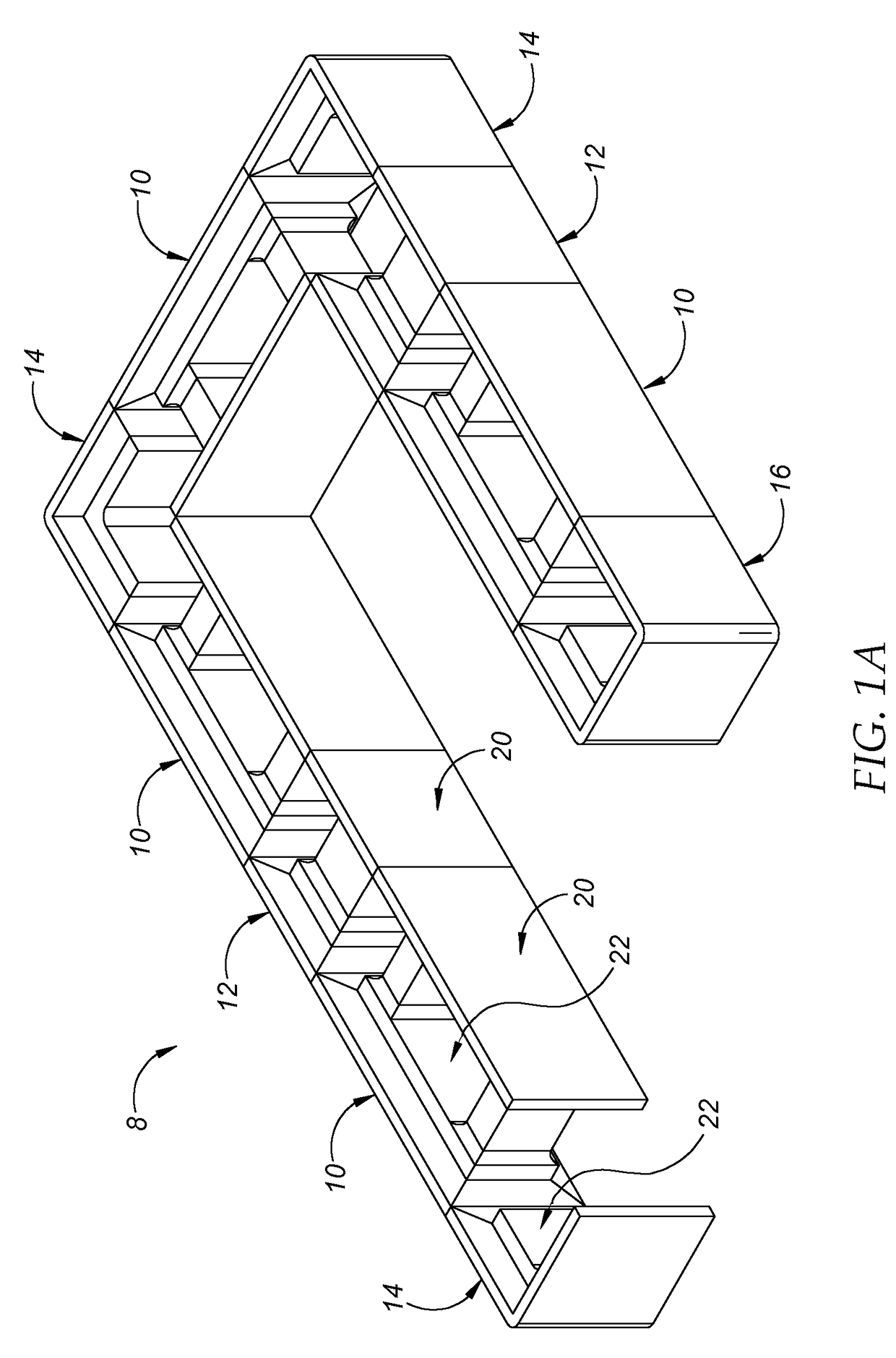
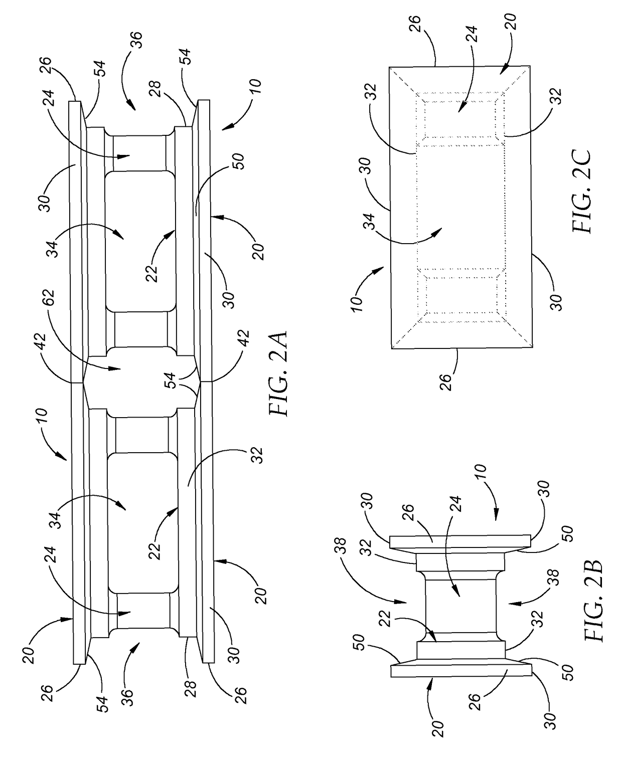
[0044]A representative embodiment of an interlocking mortarless structural concrete block building system 8 is illustrated in FIGS. 1A-1B. A basic block layout encompassing straight walls, corners, and ends is shown in perspective in FIG. 1A and the same layout is shown in a top view in FIG. 1B. The system 8 is designed for assembly in which a plurality of blocks 10 are stacked in successive horizontal courses in a staggered relationship using four different block configurations. The basic repetitive unit, the runner block 10, has a length twice as long as it is wide. A half block 12 is the same width and half the length as the runner block 10. The corner block 14 has two adjacent walls of the same width as the half block. The end block 16 consists of three adjacent walls all of the same width as the runner block 10. Additional embodiments are shown in FIGS. 2, 3, 4, and 5 illustrating various units within the system. FIG. 6 shows the system 8 in use which is described in more detai...


PUM


Abstract

An interlocking modular building block system for mortarless cavity wall construction having blocks configured such that upon grouting, the cavity is solidly filled in a unified mass. Four block configurations are provided, namely runner, half, corner, and end block units. The runner has a length two times its width, and the other blocks have the same width and length as the width of the runner. Common to all blocks is a pair of parallel offset solid walls forming the outside and inside walls while creating vertical and horizontal positive and negative alignment features. The offset walls also form flat horizontal and vertical surfaces where successive units meet upon alignment. These walls are connected by one or more transverse membranes, with the exception of the corner block, where the walls are joined end to end at right angles.

Description

BACKGROUND OF THE INVENTION[0001]1. Field of the Invention[0002]This invention relates to construction materials and, more particularly, to an improved type of interlocking mortarless structural concrete building block system.[0003]2. Description of the Related Art[0004]The origin of the common concrete block in use today was meant as a component to compliment the prior primary masonry building unit, the common clay fired brick. The larger size of the concrete block created greater installation economy over brick and eventually dominated the building industry.[0005]Concrete blocks are also referred to as concrete masonry units or cmus. The majority of these blocks are produced by hydraulic press machinery and vibrated under pressure in steel molds. The final product is usually heavy and rough in texture. While most concrete block usually have vertical cellular cores, the majority of these cores are non-communicative horizontally. The open cells within a wall of this type are filled ...

Claims


Application Information

Patent Timeline
Patent Type & Authority Patents(United States)
IPC IPC(8): E04C1/00E04C1/40
CPCE04B2/54
Inventor AUGUST, JOHN
Owner AUGUST JOHN
Learn More