
Shielding arrangement for the smelt spout area of a recovery boiler

a technology for smelt spouts and recovery boilers, which is applied in the direction of curtain suspension devices, blast furnace components, blast furnaces, etc., can solve the problems of danger to personnel working and moving in the vicinity, and achieve the effect of increasing work safety

Active Publication Date: 2011-03-08
METSO POWER OY
View PDF16 Cites 4 Cited by
  • Summary
  • Abstract
  • Description
  • Claims
  • Application Information

AI Technical Summary

Benefits of technology

"The present invention provides a new solution for improving work safety in the smelt spout area of a recovery boiler. The invention involves the use of a movable shielding wall to separate the smelt spouts from the working area, which prevents possible smelt splashes and noise from reaching the working area. The shielding wall can be opened for different targeted operations and also includes inspection openings for visual monitoring and other tasks. The use of the shielding structure decreases the safety risks, improves work conditions, and enables efficient utilization of the smelt spout area."

Problems solved by technology

The possible splashes of smelt cause danger to the personnel working and moving in the vicinity.

Method used


Image

  • Shielding arrangement for the smelt spout area of a recovery boiler
  • Shielding arrangement for the smelt spout area of a recovery boiler
  • Shielding arrangement for the smelt spout area of a recovery boiler

Examples


Embodiment Construction

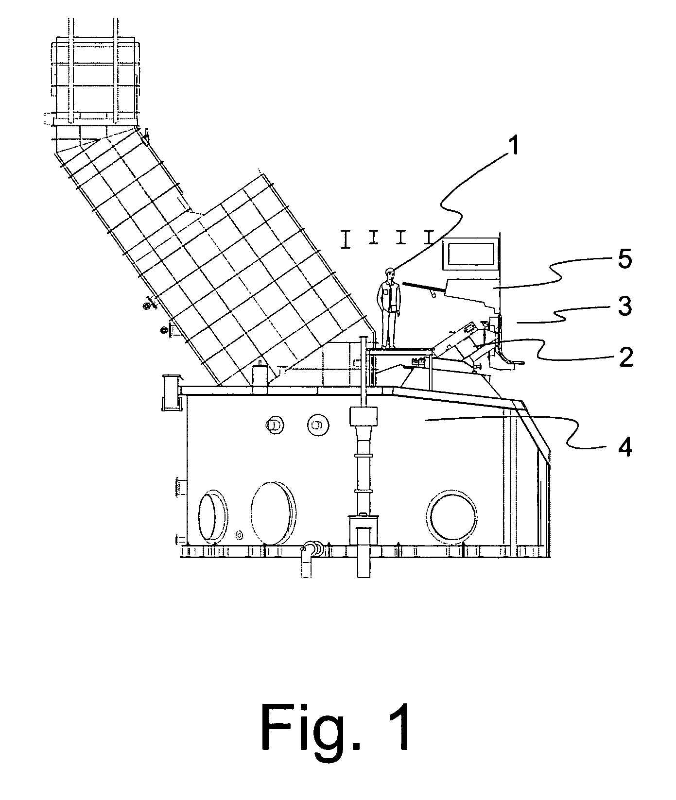
[0025]FIG. 1 shows a present smelt spout area of a recovery boiler. The area comprises smelt spouts 2, along which the smelt is directed from the furnace 3 to the dissolving tank 4. Generally in boilers the air nozzles 5 of the primary air level are placed above the smelt spouts 2 in such a manner that they can be accessed from the smelt spout area, for example, by means of some platform.

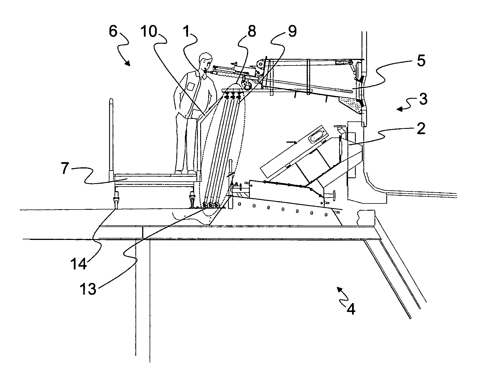
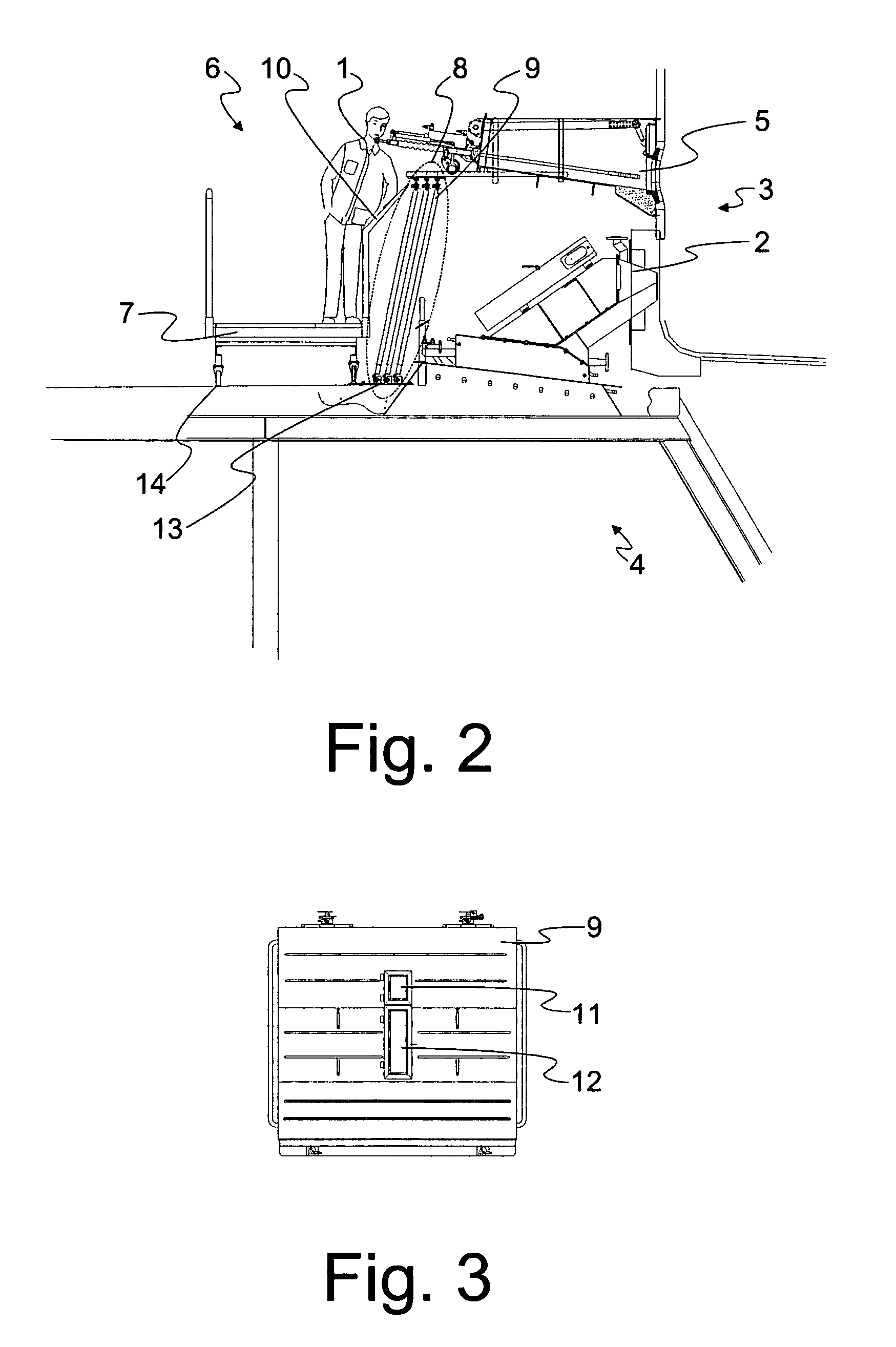
[0026]FIG. 2 shows the shielding wall 8 according to the invention in a side view. This direction is the same as the direction of the bank of smelt spouts 2, i.e. the direction of the wall of the boiler. The shielding wall 8 is arranged between the working area 6 and the smelt spouts 2. The working area 6 refers to that area of the smelt spout area, where the personnel works when performing usage, service and maintenance operation. In the case according to FIG. 2, the working area 6 is the area to the left of the shielding wall 8. In FIG. 2, inter alia, a service platform 7 is located in the working...


PUM

PropertyMeasurementUnit
areaaaaaaaaaaa
temperatureaaaaaaaaaa
heat radiationaaaaaaaaaa

Abstract

A method for improving the operation safety of the smelt spout area of a recovery boiler, which smelt spout area comprises a working area (6), as well as smelt spouts (2) connected to the lower part of the boiler for directing the smelt from the boiler to a dissolving tank (4). In the method the smelt spouts (2) are separated from the working area (6) by a shielding wall (8, 10) arranged movable in relation to the smelt spouts. The invention also relates to a smelt spout area of a recovery boiler.

Description

FIELD OF THE INVENTION[0001]The invention relates to a method for improving the operation safety of the smelt spout area of a recovery boiler and the smelt spout area of a recovery boiler.BACKGROUND OF THE INVENTION[0002]The spent lye, i.e. the so-called black liquor created in pulp manufacture is burnt in a recovery boiler, on one hand, in order to recover the energy it includes, and on the other hand, in order to recover the chemicals in it and to recycle them back to circulation. A char bed is created on the bottom of the recovery boiler when burning black liquor, which in a high temperature forms into smelt, which is removed from the boiler as a continuous flow via smelt spouts to a dissolving tank.[0003]Below the furnace is located the cover area of the dissolving tank of the recovery boiler, i.e. the smelt spout area, where the smelt from the lower part of the furnace is directed along the so-called smelt spout to the dissolving tank. FIG. 1 shows a typical smelt spout area of...

Claims


Application Information

Patent Timeline
Patent Type & Authority Patents(United States)
IPC IPC(8): C21B7/24D21CD21C11/12F22B37/48
CPCD21C11/122F22B37/48D21C11/12
Inventor HAAGA, KARIKOSKELA, HANNUSAARELA, ARI
Owner METSO POWER OY
Learn More