
Spherical dome

Active Publication Date: 2011-03-08
JACOBY JOHN DONALD
View PDF34 Cites 29 Cited by
  • Summary
  • Abstract
  • Description
  • Claims
  • Application Information

AI Technical Summary

Benefits of technology

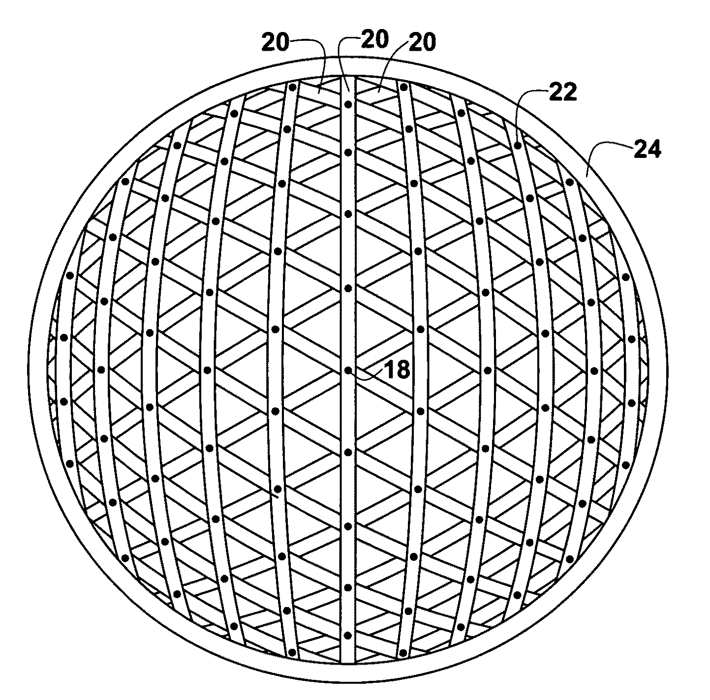
[0011]In accordance with the present invention, there is provided a spherical dome consisting of continuous prismatic members in three layers, an outer layer, a middle layer, and an inner layer. The continuous prismatic members follow great circle arcs. The members of the three layers form a three way grid, crossing at the vertices of contiguous spherical triangles. Three members, one from each layer, are connected together at each vertex with fasteners, such as bolts, rivets, or welds. The members of each layer can be spaced as desired to provide structural integrity, economy, and simplicity of construction.
[0012]A tension ring, when required structurally, is provided at the bottom periphery of the dome to resist the vertical and horizontal forces generated by the supported loads. The combined elements provide a simple and economical spherical dome.
[0014]It would also be advantageous to provide a spherical dome simple to construct.
[0015]It would further be advantageous to provide a spherical dome with simple members and connections to provide economy of construction.

Problems solved by technology

Many of them have strived for simplicity and economy, parameters which are difficult to achieve.
Despite the striving for simplicity and economy, combined with aesthetics, domes continue to be quite complex and costly.
Almost all domes, especially the larger ones, remain difficult to build, some of them requiring shoring, such as the case for concrete domes, and some of them require many different parts and connections, such as the case for structural steel domes.
Even geodesic domes have many and complex parts and connections.
Complexity with resultant high costs seem to be inherent in such structures.

Method used


Image

  • Spherical dome
  • Spherical dome
  • Spherical dome

Examples


Embodiment Construction

[0024]FIG. 1, a plan view of a three-way spherical grid pattern, shows an equatorial circle 10, a polar node 12 at six locations, great circle arcs 14, vertices of contiguous spherical triangles 16, and a central polar node 18.

[0025]To form the three-way spherical grid pattern, an equatorial circle 10 is the base. A polar node 12 is located at each of six locations, sixty degrees apart, along the equatorial circle 10. The great circle arcs 14 connect one polar node 12 to an opposite polar node 12. The great circle arcs 14 are spaced as desired for greater or less density of great circle arcs 14. They are also spaced to intersect at the vertices of contiguous spherical triangles 16. The central polar node 18 is located vertically above the center of the equatorial circle 10 and at the intersection of three great circle arcs 14.

[0026]As described, the grid of great circle arcs 14 lies within the surface of a coincident sphere. As shown, the frequency of great circle arcs 14 becomes gr...


PUM


Abstract

The invention is a spherical dome consisting of continuous prismatic members in three layers, an outer layer, a middle layer, and an inner layer. The continuous prismatic members follow great circle arcs. The members of the three layers form a three-way grid, crossing at the vertices of contiguous spherical triangles. Three members, one from each layer, are connected together at each vertex with fasteners, such as bolts, rivets, or welds.The continuous prismatic members of each layer can be spaced as desired to provide structural integrity, economy, and simplicity of construction. A tension ring, when required structurally, is provided at the bottom periphery of the dome to resist the vertical and horizontal forces generated by the supported loads. The combined elements provide a simple and economical spherical dome.

Description

FIELD OF THE INVENTION[0001]The present invention relates to dome structures and, more particularly, to dome structures with intersecting members to form contiguous spherical triangles.BACKGROUND OF THE INVENTION[0002]The construction of spherical domes has a long history. There are many types of spherical domes constructed of materials such as reinforced concrete, foam, structural steel, and even ice. Reinforced concrete and foam type domes typically require the use of forms. Structural steel domes typically require many members and connections. Of course, ice is typically used in the construction of igloos, a special case of domes.[0003]It is desirable to provide economical and simple construction for domes, especially larger domes. Costly and complex designs and construction have often been used, however there are many cases where simplicity and economy are desired and needed.[0004]Aesthetics, of course, is usually an important factor, but do not necessarily require costly, compl...

Claims


Application Information

Patent Timeline
IPC IPC(8): E04B7/08
CPCE04B1/3211E04B7/105
Inventor JACOBY, JOHN DONALD
Owner JACOBY JOHN DONALD
Learn More