
Shock absorber ankle exercise device

Inactive Publication Date: 2011-02-22
ALEXA AUSTEN
View PDF34 Cites 42 Cited by
  • Summary
  • Abstract
  • Description
  • Claims
  • Application Information

AI Technical Summary

Benefits of technology

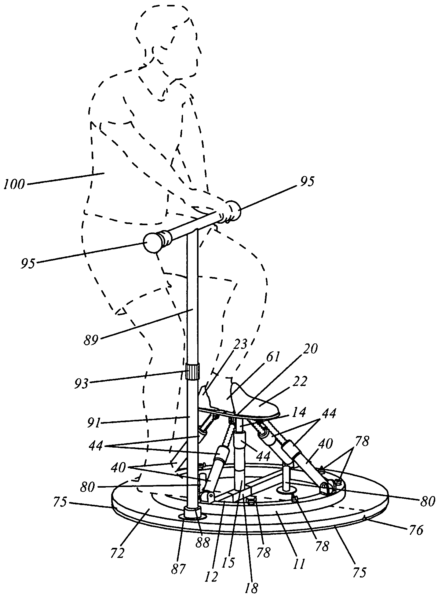
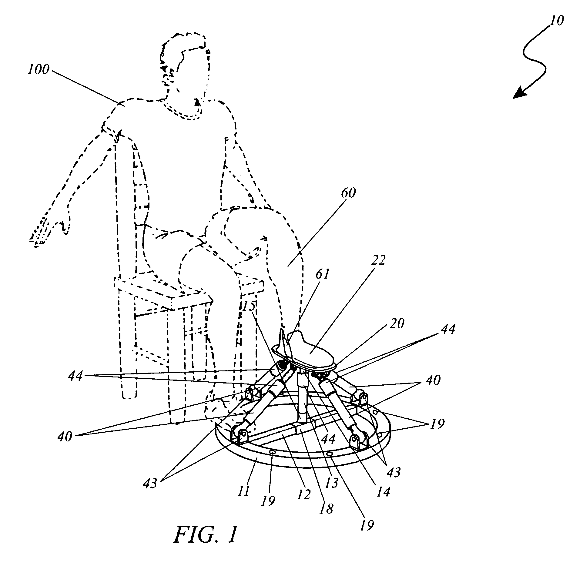
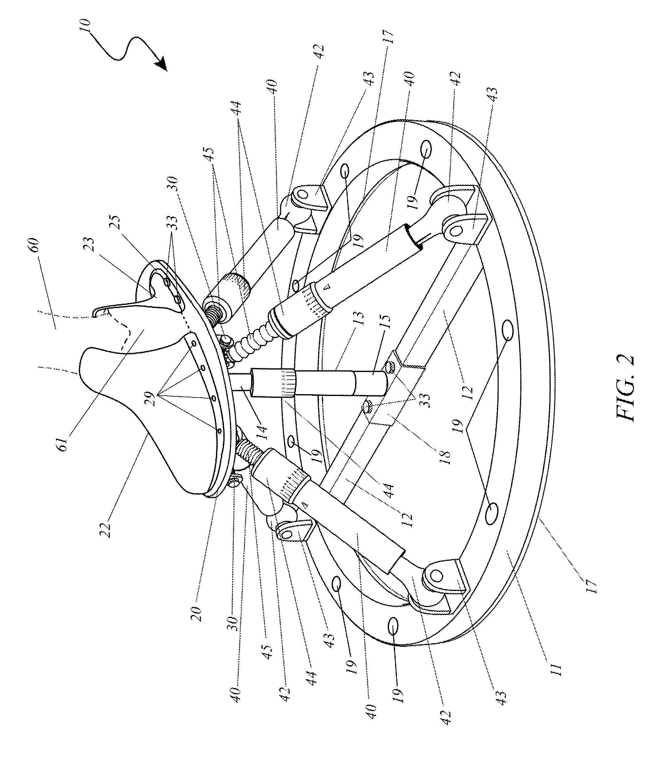
[0011]To achieve the above objectives, it is the object of the present invention to provide a unique physical exercise apparatus which is primarily designed to strengthen and develop the ankle area of the human body. The invention provides a large base for stability which sits on the floor. Four (4) hydraulic or possibly pneumatic cylinders are equidistantly spaced around the outer perimeter of the base and extend upward and inward to support a footrest. One (1) cylinder is located in the center of the base and extends upward to support the footrest. A footrest assembly is the size of a typical adult's foot and is provided with a toe cuff and size adjustable heel cuff. The user's foot is supported in a manner which provides adjustable resistance to movement in a full range of motion and thus the user is able to move their foot about against the resistance of the hydraulic or pneumatic cylinders. In doing so, the user will build strength in all muscles, tendons, ligaments and the like about the ankle area. Such a workout is envisioned to be not only beneficial for athletes, but for those who have undergone ankle surgery, and / or are trying to rehabilitate their ankle. The use of the innovative apparatus allows virtually anyone to rehabilitate or strengthen their ankle area in a manner efficiently.
[0015]Yet still another object of the present invention is to provide the apparatus including an adjustable footrest assembly supported above the base member and operably engaged with the hydraulic cylinders, and a mechanism for attaching the hydraulic cylinders to the footrest assembly and the base member. Each of the hydraulic cylinders is independently compressible along a linear path based upon an external force exerted by the user during movement along the orbital or vertical direction. The footrest assembly provides a means of length adjustment comprising toe cuff and adjustable heel cuff which enables for a larger and smaller foot.
[0020]Yet still another object of the present invention is to provide the platform assembly which provides a larger and more stable transportable structure for the base to securely attach during use. The base can be temporally mounted to the platform assembly during use by a plurality of wing bolt fasteners and wing bolt apertures which align with the base anchoring apertures to secure the base to the platform. The platform assembly also comprises a large platform hinge which provides a means of collapsing the platform for convenient storage and ease of transport.
[0021]Yet still another object of the present invention is to provide a stabilizing handle assembly which removably attaches to the platform and provides the user with the ability to use the use the ankle exercise apparatus in a standing position by providing a posture support to the user. The handle assembly connects to a mounting bracket on a top surface of the platform assembly. In such a manner the additional benefit of being able to utilize the invention in a seated or a standing position is provided.
[0022]Yet still another object of the present invention it to provide a an unexpected benefit of allowing a user to selectively rehabilitate their ankle by rotating their lower leg along an orbital, vertical, and rotational path such that independent tension is exerted on the muscles to improve the strength and coordination of major muscle groups at the ankle.

Problems solved by technology

Unfortunately, the shape of the base of this prior art example does not provide a stable platform for use of the invention.
Unfortunately, this prior art example requires the user to stand on one (1) foot while exercising the other foot which may not be feasible for a person with an injury to both legs or feet.
Unfortunately, this prior art example is not designed for rehabilitation of an ankle from an injury.
Unfortunately, this prior art example provides a severely restricted range of exercise motion.
None of the prior art particularly describes a shock absorption apparatus for developing, strengthening or rehabilitating the human ankle.

Method used


Image

  • Shock absorber ankle exercise device
  • Shock absorber ankle exercise device
  • Shock absorber ankle exercise device

Examples


Embodiment Construction

[0034]The best mode for carrying out the invention is presented in terms of its preferred embodiment, herein depicted within FIGS. 1 through 6b. However, the invention is not limited to the described embodiment and a person skilled in the art will appreciate that many other embodiments of the invention are possible without deviating from the basic concept of the invention, and that any such work around will also fall under scope of this invention. It is envisioned that other styles and configurations of the present invention can be easily incorporated into the teachings of the present invention, and only one particular configuration shall be shown and described for purposes of clarity and disclosure and not by way of limitation of scope.

[0035]The terms “a” and “an” herein do not denote a limitation of quantity, but rather denote the presence of at least one of the referenced items.

[0036]The present invention describes an apparatus and method that strengthens, develops, and / or rehabi...


PUM


Abstract

An apparatus and method designed to strengthen, develop, and rehabilitate the anatomy of the human ankle is herein disclosed, comprising a large stable floor base and a plurality of resistant shock absorber-like members extending therefrom a foot securing platform. A user's foot is placed thereon and connected thereto the foot platform by toe and heel cuffs. Each motion resistant cylinder has adjustment means for reducing or adding resistance. In use, the attached lower leg and foot is restrained in all planar and vertical axes; however, the user is able to move their foot in a vertical and orbital manner against the resistance of the cylinders resulting in rehabilitation and / or strengthening of the muscles, tendons and ligaments surrounding the ankle. Improving ankle strength and mobility using this apparatus would have athletic, fitness, and therapeutic benefits.

Description

RELATED APPLICATIONS[0001]This present invention is a continuation-in-part application of Ser. No. 11 / 810,808 filed Jun. 7, 2007 now abandoned; which in turn is a complete application claiming benefit of U.S. Provisional 60 / 811,462 filed Jun. 7, 2006.FIELD OF THE INVENTION[0002]The present invention relates generally to a physical exercise apparatus and, more particularly, to a shock absorption apparatus for developing, strengthening or rehabilitating the human ankle.BACKGROUND OF THE INVENTION[0003]The present invention relates generally to a physical exercise apparatus and, more particularly, to a shock absorption apparatus for developing, strengthening or rehabilitating the human ankle.[0004]Physical fitness and health concerns are among the areas of highest concern among Americans today. More than ever, people are frequenting health clubs and performing exercise routines at home in order to lose weight, improve muscle tone and maintain a healthy lifestyle. One (1) area of the bo...

Claims


Application Information

Patent Timeline
IPC IPC(8): A63B21/008A63B23/08
CPCA63B21/0083A63B23/08A63B23/085A63B21/4015A63B23/03508A63B21/00072A63B21/00069A63B21/0087A63B2208/0209A63B2210/50A63B2225/09A63B2208/0233
Inventor ALEXA, AUSTEN
Owner ALEXA AUSTEN
Learn More