
Key duplication machine

a key duplication machine and key technology, applied in the field of keys duplication machines, can solve the problems of increasing the difficulty in many are not readily distinguishable from each other, and businesses that offer key cutting services are not staffed by experienced locksmiths capable of consistently and accurately identifying the proper key blank

Active Publication Date: 2011-02-22
HY KO PRODS
View PDF38 Cites 66 Cited by
  • Summary
  • Abstract
  • Description
  • Claims
  • Application Information

AI Technical Summary

Benefits of technology

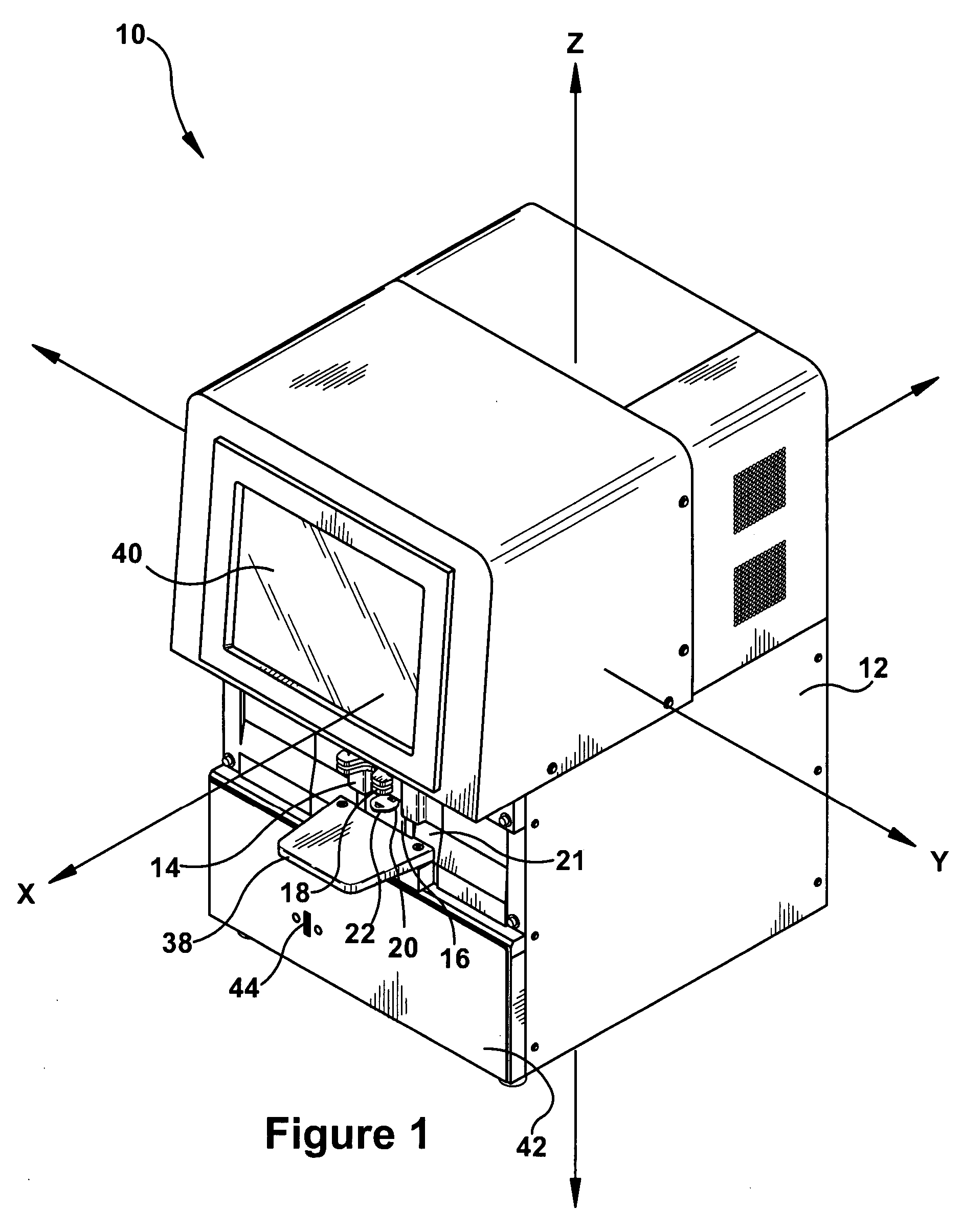
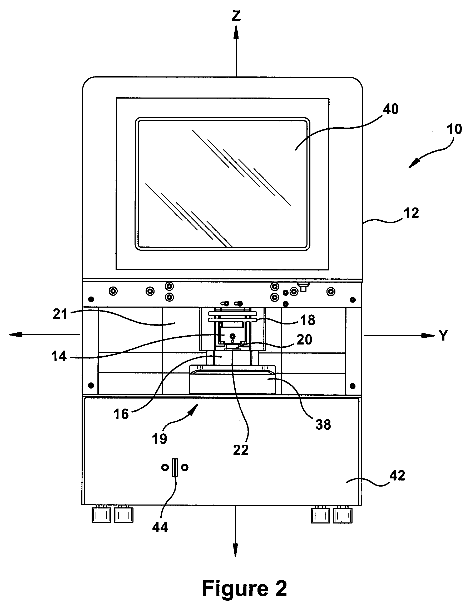
"The patent describes an apparatus and methods for duplicating a master key. It includes an optical imaging device, logic, clamping assembly, and cutting member. The optical imaging device captures an optical image of the master key, the logic identifies the key pattern of the master key from the image, the clamping assembly secures a key blank, and the cutting member cuts the key pattern into the key blank. The technical effect of this invention is to provide a convenient and efficient way to duplicate keys."

Problems solved by technology

There are numerous key blanks, and many are not readily distinguishable from each other.
Identifying the correct key blank for use in duplication often requires visually examination of a plurality of key blanks, where differences between key blanks may be very subtle, significantly increasing the level of difficulty in identifying the proper key blank.
All too often, businesses that offer key cutting services are not staffed by experienced locksmiths capable of consistently and accurately identifying the proper key blank to be used.
Instead, an employee is shown how to “eyeball” what is thought to be the correct blank and then cut a duplicate key at the substantial risk of the key working improperly.
Often, such errors are not identified until after the customer leaves the store, thus resulting in frustration with the retailer due to an unsuccessful key cut.
Although prior art key duplication machines and processes are well established and widely utilized, such machines and processes produce a relatively high scrap rate, overly rely on the experience and judgment of machine operators, and may not allow for evaluation of the accuracy of a duplicate key without the duplicate key being tested in its associated lock.

Method used


Image

  • Key duplication machine
  • Key duplication machine
  • Key duplication machine

Examples


Embodiment Construction

[0039]The Detailed Description of the Invention merely describes embodiments of the invention and is not intended to limit the scope of the claims in any way. Indeed, the invention as described by the claims is broader than and unlimited by the preferred embodiments, and the terms in the claims have their full ordinary meaning.

[0040]As described herein, apparatus and methods can be designed to produce accurate and reliable duplicates of master keys. In one embodiment, the duplication of a master key is facilitated by the capture of an optical image of a profile or silhouette of the master key, including the key pattern of the master key, and the capture of a profile or silhouette of a key blank. As will be further described herein, the captured images may be analyzed by logic to determine the proper key blank to be used for a duplicate key, validate the selection of the proper key blank, facilitate the accurate cutting of the key pattern of the master key into the key blank, and val...


PUM

PropertyMeasurementUnit
opticalaaaaaaaaaa
optical imageaaaaaaaaaa
widthaaaaaaaaaa

Abstract

Apparatus, methods, and other embodiments associated with a key duplication machine are described. In one embodiment, an assembly for duplicating a master key includes an optical imaging device, a logic, a clamping assembly, and a cutting member. The optical imaging device is capable of capturing an optical image of at least a portion of the master key. The logic is capable of determining a key pattern of the master key from the optical image of the master key. The clamping assembly is capable of clamping a key blank and the cutting member is capable of cutting a key pattern into said key blank.

Description

CROSS REFERENCE TO RELATED APPLICATION[0001]This non-provisional application claims the benefit of U.S. Provisional Patent Application No. 60 / 761,293, titled “KEY DUPLICATION MACHINE,” filed Jan. 23, 2006, which is hereby incorporated in its entirety.FIELD OF INVENTION[0002]This invention relates generally to apparatus and methods for duplicating keys, and more specifically, this invention relates to apparatus and methods for cutting duplicate keys based on a captured image of a master key.BACKGROUND[0003]Key duplication and key cutting machines are designed to reproduce a key pattern of a master key onto a key blank. Prior art key duplication and key cutting machines typically determine the key pattern of a master key by mechanically engaging the key pattern of a master key with a stylus, tracer bar, or other such mechanical member. For example, prior art key duplication machines typically comprise a pair of clamps or vise grips mounted on a carriage. A master key, having a key pat...

Claims


Application Information

Patent Timeline
Patent Type & Authority Patents(United States)
IPC IPC(8): B23C3/35G06V10/145G06V10/46G06V10/60
CPCB23C3/35G06K9/2036G06K9/20G06K9/48G06K9/4661B23B2270/32B23C2235/08B23C2235/12B23C2235/41G06K2209/401Y10T409/303808Y10T409/300952Y10T409/301008G07F17/26G06Q20/18G06V10/145G06V10/60G06V10/46G06V2201/121G06V20/66B23C2235/32
Inventor BASS, MICHAEL A.MUTCH, WILLIAM R.RYAI, SR., RICHARD W.THOMPSON, CHESTER O. D.DRAKE, ROBERT E.PORRAS, RANDALL A.
Owner HY KO PRODS
Learn More