
RFOG with reduced polarization mode induced bias error

a polarization mode and error-induced technology, applied in the field of resonance fiber optic gyroscopes, can solve the problems of reducing the accuracy of rfog, severely limiting the polarization sensing, and cross-coupling in the coupling optics still excite the second undesirable polarization state in the pm fiber, so as to effectively reduce the polarization errors and cancel out the polarization error induced bias

Active Publication Date: 2011-02-15
HONEYWELL INT INC
View PDF3 Cites 4 Cited by
  • Summary
  • Abstract
  • Description
  • Claims
  • Application Information

AI Technical Summary

Benefits of technology

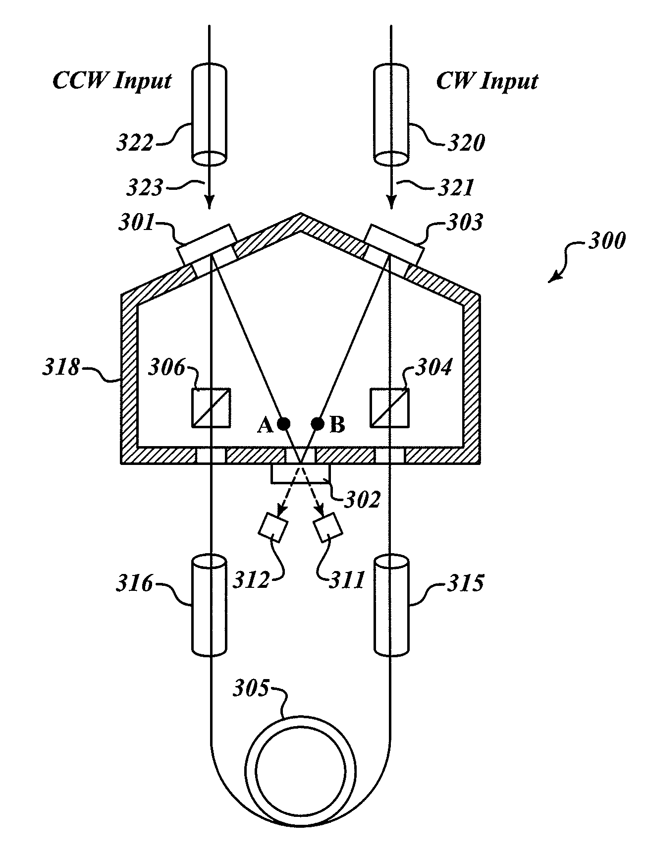
[0008]In this invention, new theoretical expressions to precisely evaluate the impact of polarization error on bias are first deduced. The theory is then applied to an exemplary embodiment of hollow core fiber RFOG having an M-shape three-mirror configuration. The simulation results find that the three-mirror resonator is advantageous to achieve a possibly symmetric resonator configuration that helps to cancel out polarization error induced bias of the RFOG even when the second ESOP is present. The effectiveness of insertion of polarizing elements in the resonator and minimizing misalignment angles between all the optical component's polarization axes are evaluated by the theory for mitigation of polarization errors. In addition, the theory shows that using optical components (e.g. mirrors and couplers) with identical reflectivities and losses for different polarization modes (e.g. the horizontal- and vertical-polarized light) can effectively reduce the polarization errors. The smaller incident angle on the mirrors in the M-shaped resonator helps to obtain identical dielectric mirror reflectivity for light with different polarization states. At last, several two mirror hollow core fiber resonators are suggested as embodiments of the invention.

Problems solved by technology

This is the cause of the so called polarization errors in the rotation sensing.
Polarization induced errors may severely limit the accuracy of the RFOG.
However, cross-couplings in the coupling optics will still excite the second undesirable polarization state in the PM fiber.
The difference in speed of light between light traveling on the two principle axes of polarization in the PM fiber typically varies with temperature, leading to bias instability induced by polarization errors.

Method used


Image

  • RFOG with reduced polarization mode induced bias error
  • RFOG with reduced polarization mode induced bias error
  • RFOG with reduced polarization mode induced bias error

Examples


Embodiment Construction

[0022]In a resonator fiber optic gyroscope, a monochromatic light source is phase modulated before being coupled into the resonator. After sinusoidal phase modulation of Φm=M sin ωmt, the lightwave field becomes

[0023]Ei⁢⁢n⁡(t)=12⁢E0⁢ⅇⅈθ⁡(t)⁢exp⁡(ⅈωc⁢t)⁢exp⁡(ⅈ⁢⁢M⁢⁢sin⁢⁢ωm⁢t)+c.c.(1)

[0024]Here, E0 is the input light field amplitude, ωm is the phase modulation angular frequency (all angular frequencies will be referred to as frequencies in the following for simplicity), M is the phase modulation amplitude in unit of radians, ωc is the lightwave central frequency, and θ(t) is the initial phase of the lightwave at time t, and c.c. stands for complex conjugation of the term on the immediate left. The instantaneous frequency of the modulated light is obtained by differentiating its phase with time, which is ω(t)=ωc+Mωm cos ωmt. Using the relation of

[0025]exp⁡(ⅈ⁢⁢z⁢⁢sin⁢⁢x)=∑n=-∞∞⁢Jn⁡(z)⁢exp⁡(ⅈ⁢⁢n⁢⁢x),Eq.⁢(1)

can be expanded in terms of Bessel functions Jn

[0026]Ei⁢⁢n⁡(t)=12⁢E0⁢ⅇⅈ⁢⁢θ⁡(t)⁢∑n=-...


PUM


Abstract

Hollow core fiber RFOG having symmetric M-(or W-)shape, three-(or two-)mirror configurations. These symmetric configurations help to cancel out polarization error induced bias of the RFOG even when light of the unwanted ESOP is present. The RFOG resonator with optical components forming substantially small cross-coupling angles between their polarization axes, and / or with polarizing elements inserted into the resonator, and / or with resonator mirrors having identical reflectivity for light of different polarization states, can effectively reduce the polarization mode induced bias error.

Description

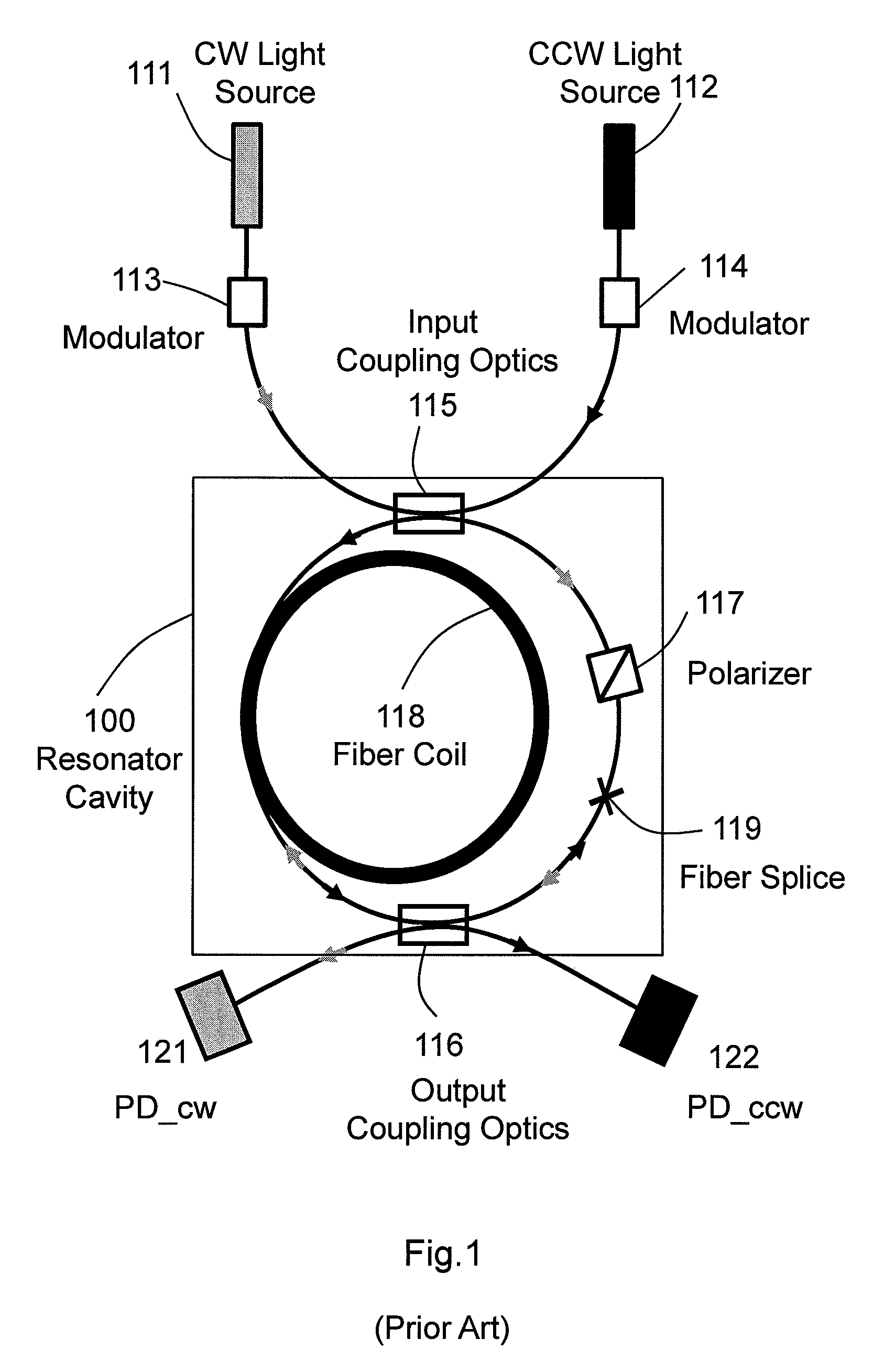
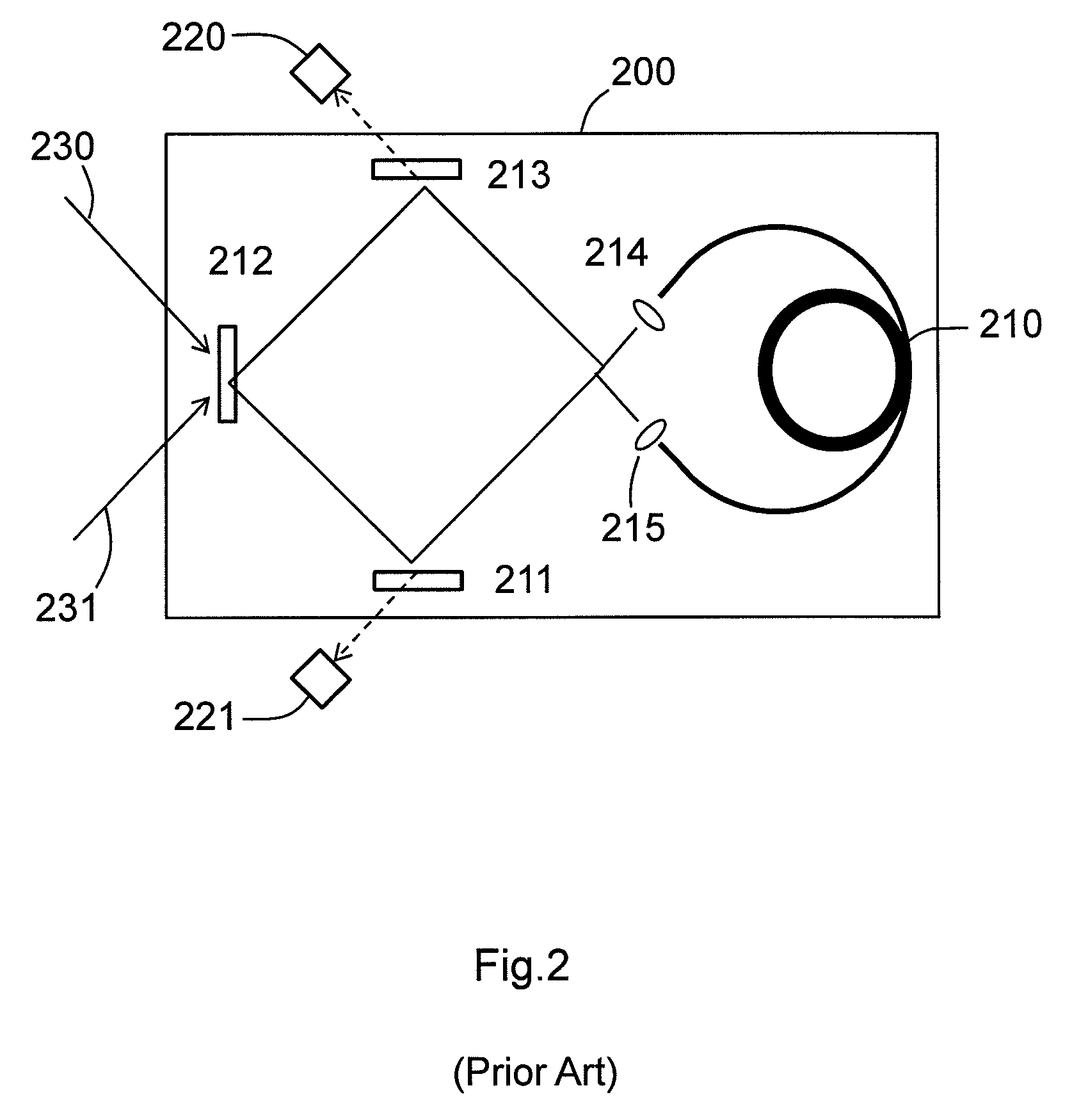
BACKGROUND OF THE INVENTION[0001]A typical resonator fiber optic gyroscope (RFOG) is a rotation rate measurement apparatus that uses a recirculating ring resonant cavity to enhance the rotation-induced Sagnac effect. FIG. 1 is a typical RFOG optical circuit, which includes monochromatic light sources 111 and 112, a ring resonator cavity 100 having an optical fiber coil 118, and input and output coupling optical components 115 and 116 for coupling the monochromatic lightwaves into and out of the cavity. The coupling optical components may be optical directional couplers and / or mirrors. When the optical path of the resonator includes both optical fibers and free space, collimator lenses may be needed to couple lightwaves in the optical fiber with the optical beams in free space (not shown in FIG. 1). Other optical components, like a polarizer 117, may be used in the resonator to improve gyro performance. For rotation sensing, monochromatic lightwaves are phase- or frequency-modulated ...

Claims


Application Information

Patent Timeline
Patent Type & Authority Patents(United States)
IPC IPC(8): G01C19/72
CPCG01C19/727
Inventor QIU, TIEQUNSANDERS, GLEN ASTRANDJORD, LEE
Owner HONEYWELL INT INC
Learn More