
Method and system for image reconstruction

a technology of image reconstruction and image, applied in the field of image reconstruction, can solve the problems of increasing the number of iterations and hence computation time, the cost of greatly increasing the computation time for reconstructing images, and the significant computational cost of targeting the reconstruction of a small area

Active Publication Date: 2011-02-08
PURDUE RES FOUND INC +3
View PDF10 Cites 36 Cited by
  • Summary
  • Abstract
  • Description
  • Claims
  • Application Information

AI Technical Summary

Problems solved by technology

While these techniques have provided large advances in diagnostic capability, it has come at the cost of greatly increased computation time to reconstruct the images when compared with traditional single-pass methods such as FBP.
When a given technique encounters a data type that it is less efficient, the number of iterations and hence computation time, increases.
However, this implies significant computational cost for targeted reconstruction of a small area.

Method used


Image

  • Method and system for image reconstruction
  • Method and system for image reconstruction
  • Method and system for image reconstruction

Examples


Embodiment Construction

Definitions

[0023]Where the definition of terms departs from the commonly used meaning of the term, applicant intends to utilize the definitions provided below, unless specifically indicated.

[0024]As used herein, the term “image space” refers to a set of vectors arranged in an array for use with a method of the present invention. The array may be of any number of dimensions, such as two-dimensional, three-dimensional, four-dimensional, for example. An example of an image space that may be used in a method described herein is a set of all possible images representable on a lattice of a given dimension. A single element (vector) of the set of the image space may be viewed on a visual display apparatus to allow a user to gain information of the interior of a scanned object.

[0025]As used herein, the term “forward model” refers to a description of the transformation from the image space of a scanned object to the projection space for a scanned object, as modeled after the operation of the...


PUM


Abstract

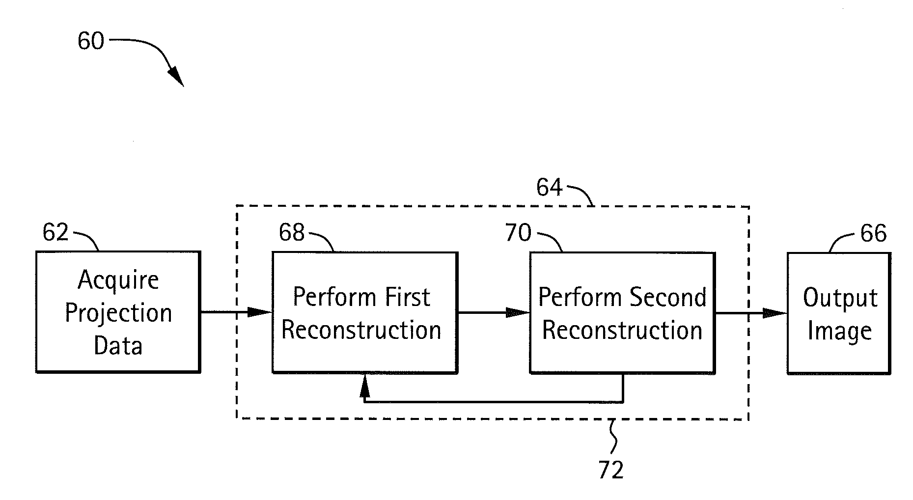
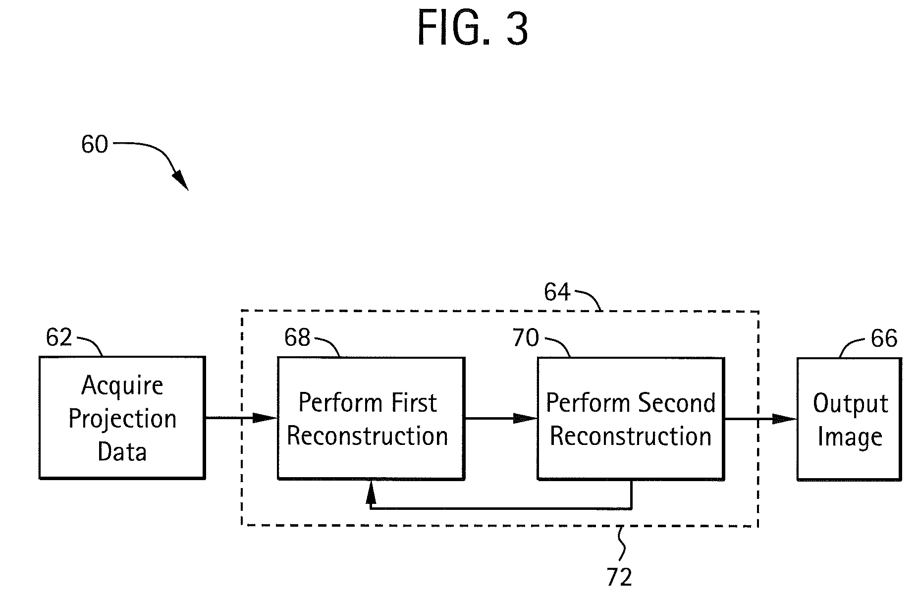
A method and system for image reconstruction of data acquired by a device such as computed tomography is provided. The method and system use a multi-stage statistical iterative reconstruction techniques to provide a three dimensional representation of the scanned object. In one embodiment, the first stage uses a projection-based reconstruction technique, such as Ordered Subset (OS) to converge on a solution for low frequency portion of the image. A subsequent stage uses a voxel-based reconstruction technique, such as Iterative Coordinate Descent (ICD), to converge on a solution for high frequency portions of the image. Systems and methods for reconstructing images from incomplete or partial projection data is also provided.

Description

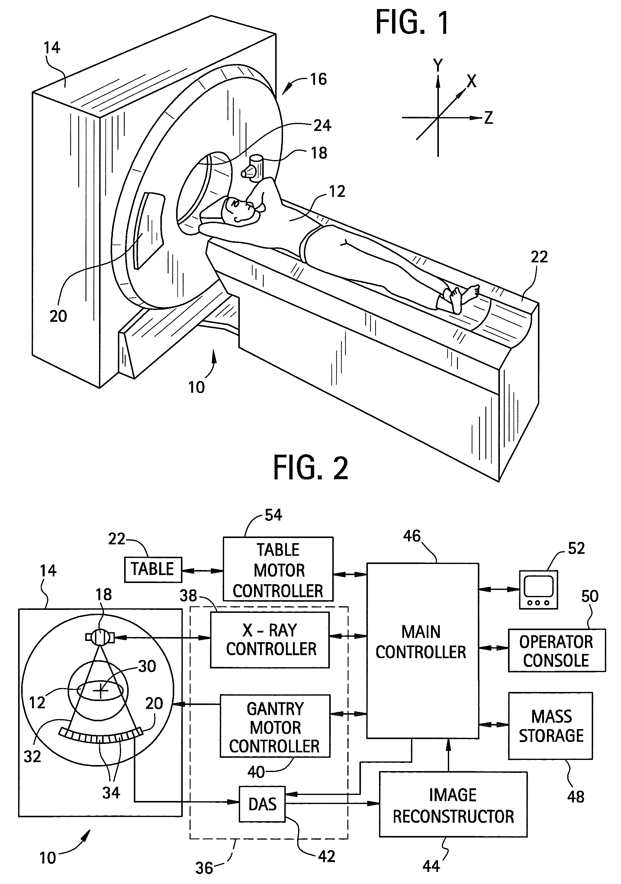
FIELD OF THE INVENTION[0001]The disclosure relates generally to imaging systems and particularly to systems and methods of reconstructing an image using multiple techniques.BACKGROUND OF THE INVENTION[0002]A computed tomography (CT) imaging system typically includes an x-ray source that projects fan- or cone-shaped x-ray beams through an object being imaged, such as a patient, to an array of radiation detectors. The beam is collimated to lie within an X-Y plane, or a set of such planes generally referred to as the “imaging planes.” Intensity of radiation from the beam received at the detector array depends on attenuation of the x-ray beam by the object. Attenuation measurements from each detector are acquired separately to produce a transmission profile.[0003]The x-ray source and the detector array are rotated within a gantry and around the object to be imaged so that a projection angle at which the x-ray beam intersects the object constantly changes. A group of x-ray attenuation me...

Claims


Application Information

Patent Timeline
Patent Type & Authority Patents(United States)
IPC IPC(8): A61B6/00
CPCG06T11/006G06T2211/424
Inventor THIBAULT, JEAN-BAPTISTEBOUMAN, CHARLES ADDISONFESSLER, JEFFREY ALLENSAUER, KEN DAVID
Owner PURDUE RES FOUND INC
Learn More