
Lower power battery-assisted RFID tag having improved recognition distance, and wake-up method thereof

a low-power, battery-assisted technology, applied in the direction of burglar alarm mechanical actuation, burglar alarm by hand-portable object removal, instruments, etc., can solve the problems of limited battery life, unreliable recognition, limited recognition distance, etc., and achieve the effect of improving the recognition distan

Inactive Publication Date: 2011-02-08
ELECTRONICS & TELECOMM RES INST
View PDF18 Cites 7 Cited by
  • Summary
  • Abstract
  • Description
  • Claims
  • Application Information

AI Technical Summary

Benefits of technology

The solution enhances recognition distance and reduces power consumption by ensuring the RFID tag only consumes power when necessary, improving communication reliability and extending the tag's operational range.

Problems solved by technology

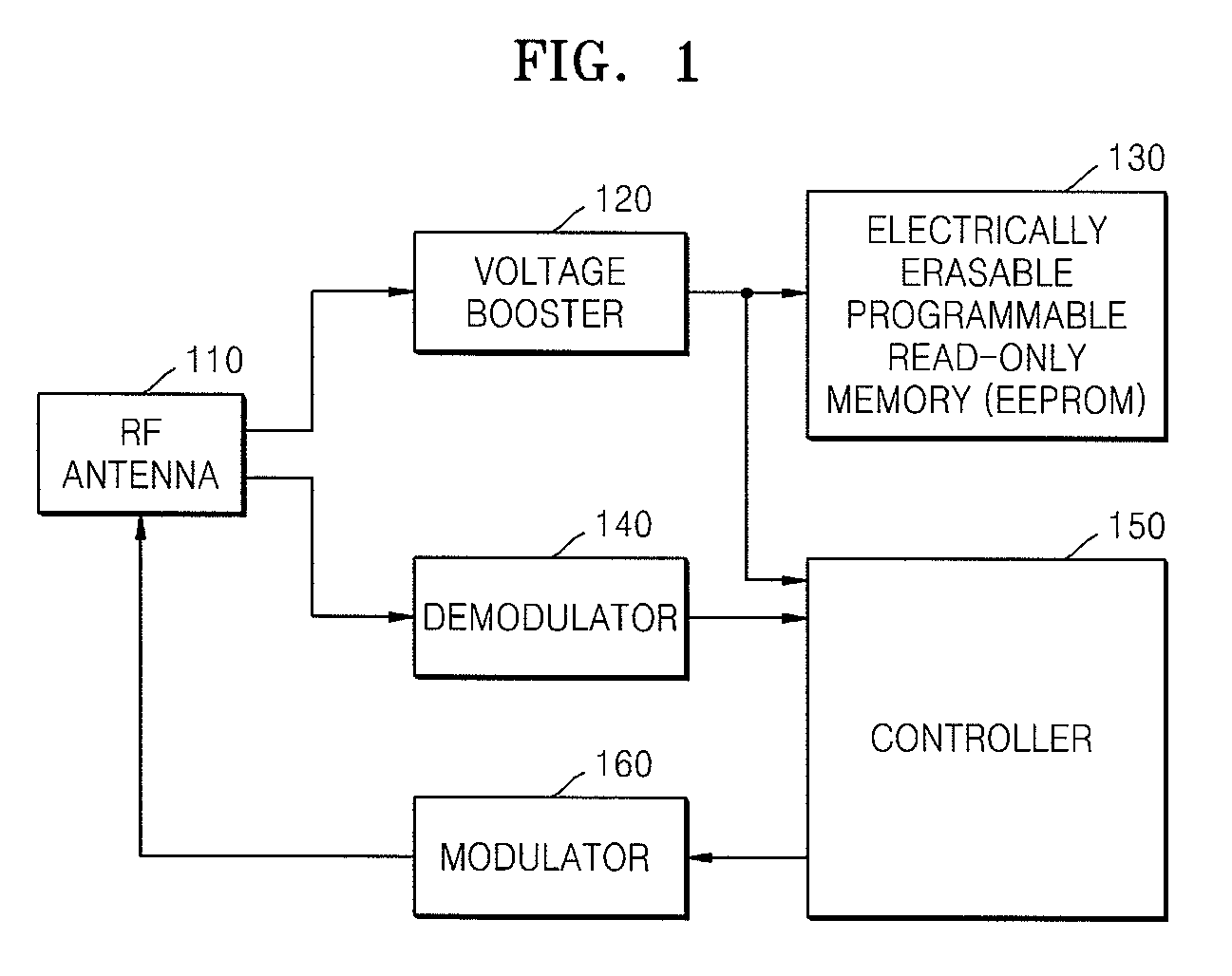
Therefore, the recognition distance is limited to about 5 m, and recognition is unreliable when the tag is attached to a metal object.
Meanwhile, active and semi-active tags are battery-assisted, and thus have longer recognition distance than passive tags, but suffer from limited battery lifespan.

Method used


Image

  • Lower power battery-assisted RFID tag having improved recognition distance, and wake-up method thereof
  • Lower power battery-assisted RFID tag having improved recognition distance, and wake-up method thereof
  • Lower power battery-assisted RFID tag having improved recognition distance, and wake-up method thereof

Examples


Embodiment Construction

[0023]The present invention will now be described more fully with reference to the accompanying drawings, in which exemplary embodiments of the invention are shown. The invention may, however, be embodied in many different forms, and should not be construed as being limited to the embodiments set forth herein; rather, these embodiments are provided so that this disclosure will be thorough and complete, and will fully convey the concept of the invention to those skilled in the art.

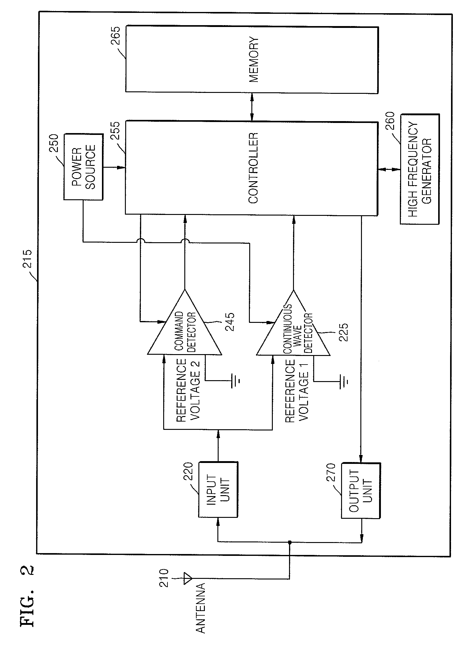
[0024]FIG. 2 is a functional block diagram of a radio frequency identification (RFID) tag according to an embodiment of the present invention.

[0025]Referring to FIG. 2, when a signal (including a continuous wave and a command) is received by an RFID tag 215 from an RFID tag reader, an input unit 220 rectifies and boosts the signal to output a direct-current voltage. A continuous wave detector 225 compares the direct-current voltage with a reference voltage to detect the continuous wave. Since this is an onl...


PUM


Abstract

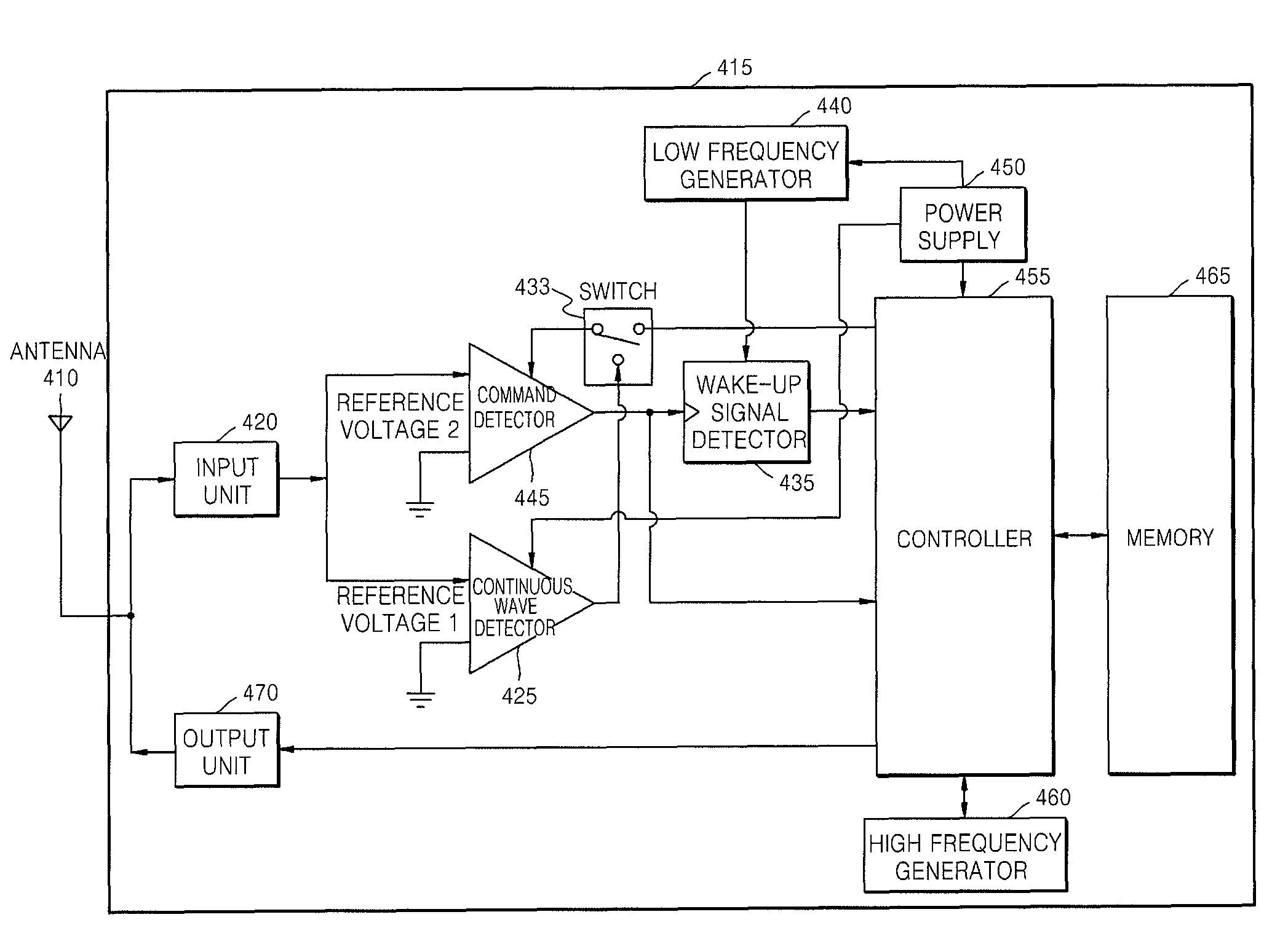
Provided are a radio frequency identification (RFID) tag and a wake-up method thereof. The RFID tag includes: a power source that supplies a driving voltage; a continuous wave detector that receives the driving voltage from the power supply so as to detect a continuous wave in a signal received from an RFID tag reader; a command detector that selectively receives the driving voltage and detects a command in the signal; and a controller that executes the command detected by the command detector by supplying the driving voltage to the command detector if the continuous wave is detected, and stops the driving voltage from being supplied to the command detector if no command is received from the command detector for a predetermined time period.

Description

CROSS-REFERENCE TO RELATED PATENT APPLICATION[0001]This application claims the benefit of Korean Patent Application No. 10-2006-0118570, filed on Nov. 28, 2006, in the Korean Intellectual Property Office, the disclosure of which is incorporated herein in its entirety by reference.BACKGROUND OF THE INVENTION[0002]1. Field of the Invention[0003]The present invention relates to a radio frequency identification (RFID) tag, and more particularly, to a battery-assisted tag driven by an internal power source for improved recognition distance, and a wake-up method thereof.[0004]This work was supported by the IT R&D program of MIC / IITA. [2005-S-106-02, Development of Sensor Tag and Sensor Node Technologies for RFID / USN][0005]2. Description of the Related Art[0006]Generally, in a radio frequency identification (RFID) technique, tags are attached to respective objects, and unique identifications (IDs) of the objects are wirelessly recognized so that corresponding information can be collected, ...

Claims


Application Information

Patent Timeline
Patent Type & Authority Patents(United States)
IPC IPC(8): G08B13/14
CPCG06K19/0705G06K19/07749G06K19/07H04B1/59
Inventor JUNG, JAE-YOUNGSON, HAE WONSEO, JONG HYUNYEO, JUNHOCHOI, GIL YOUNGKIM, NAE SOOPYO, CHEOL SIGCHAE, JONG SUK
Owner ELECTRONICS & TELECOMM RES INST
Learn More