
Deployable power supply system

a power supply system and self-contained technology, applied in emergency power supply arrangements, cell components, cell component details, etc., can solve the problems of affecting the delivery of power, affecting the efficiency of power supply, and affecting the availability of power, so as to facilitate the diffusion and adoption of renewable energy, facilitate the operation, scale, maintain and transport, and facilitate assembly, service and transportation.

Inactive Publication Date: 2011-02-08
ZEROBASE ENERGY
View PDF50 Cites 31 Cited by
  • Summary
  • Abstract
  • Description
  • Claims
  • Application Information

AI Technical Summary

Benefits of technology

The system provides a reliable, clean, and efficient power solution for various applications, reducing emissions and noise, and enabling rapid deployment of renewable energy in areas without existing infrastructure, suitable for emergency and long-term use without fuel delivery, and can be easily transported and scaled as needed.

Problems solved by technology

Traditional portable generators exist for such instances; however, they are bound to fossil-fuel energy sources that may not be available in sufficient supply for extended periods of time.
Traditional back-up power products, based on fossil fuels, are problematic.
Issues of fuel delivery, maintenance, noise, and emissions restrict their feasibility and hamper the delivery of power to those who need it.
Traditional renewable energy installations are complex projects involving the purchase and integration of multiple components in customized configurations.
Solar energy projects, for one, require long lead times, professional analysis of installation sites, and the purchase of difficult-to-integrate power generation and management systems that, once installed, are permanent and difficult to expand.
Attempts have been made to design portable power supplies including renewable energy sources; however, they are of limited desired commercial interest for a variety of deficiencies.
One limitation is that they are custom structures of unique design for specific applications.
Another limitation is that they are not readily integrated into existing power transfer systems.
Yet another limitation is the portable container used to contain the power source components.
They may not be appropriately formed or fabricated to make them convenient for use or movement, they may not be suitable for protecting the internal components in the environments to be experienced, or a combination of both limitations.

Method used


Image

  • Deployable power supply system
  • Deployable power supply system
  • Deployable power supply system

Examples


Embodiment Construction

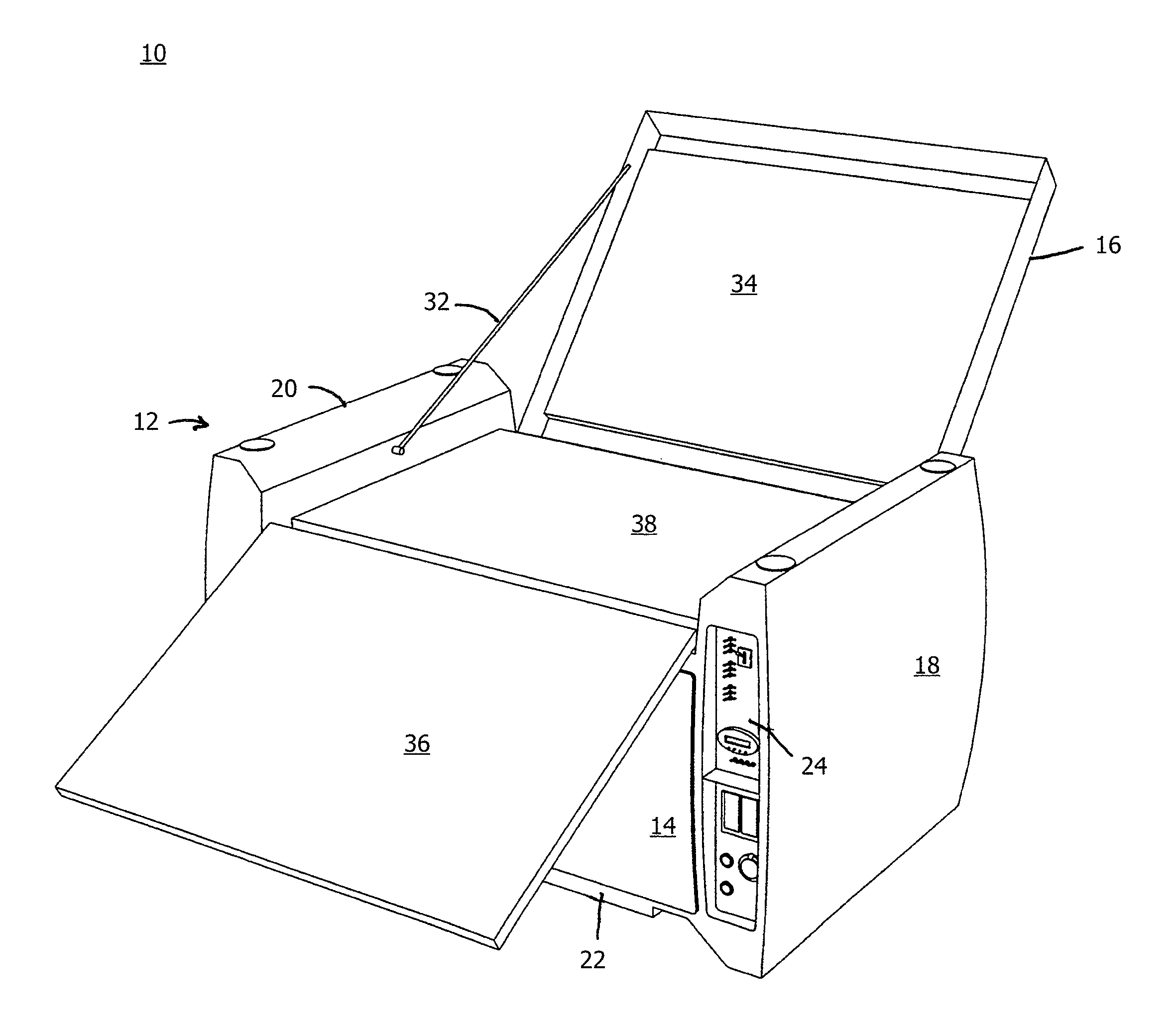
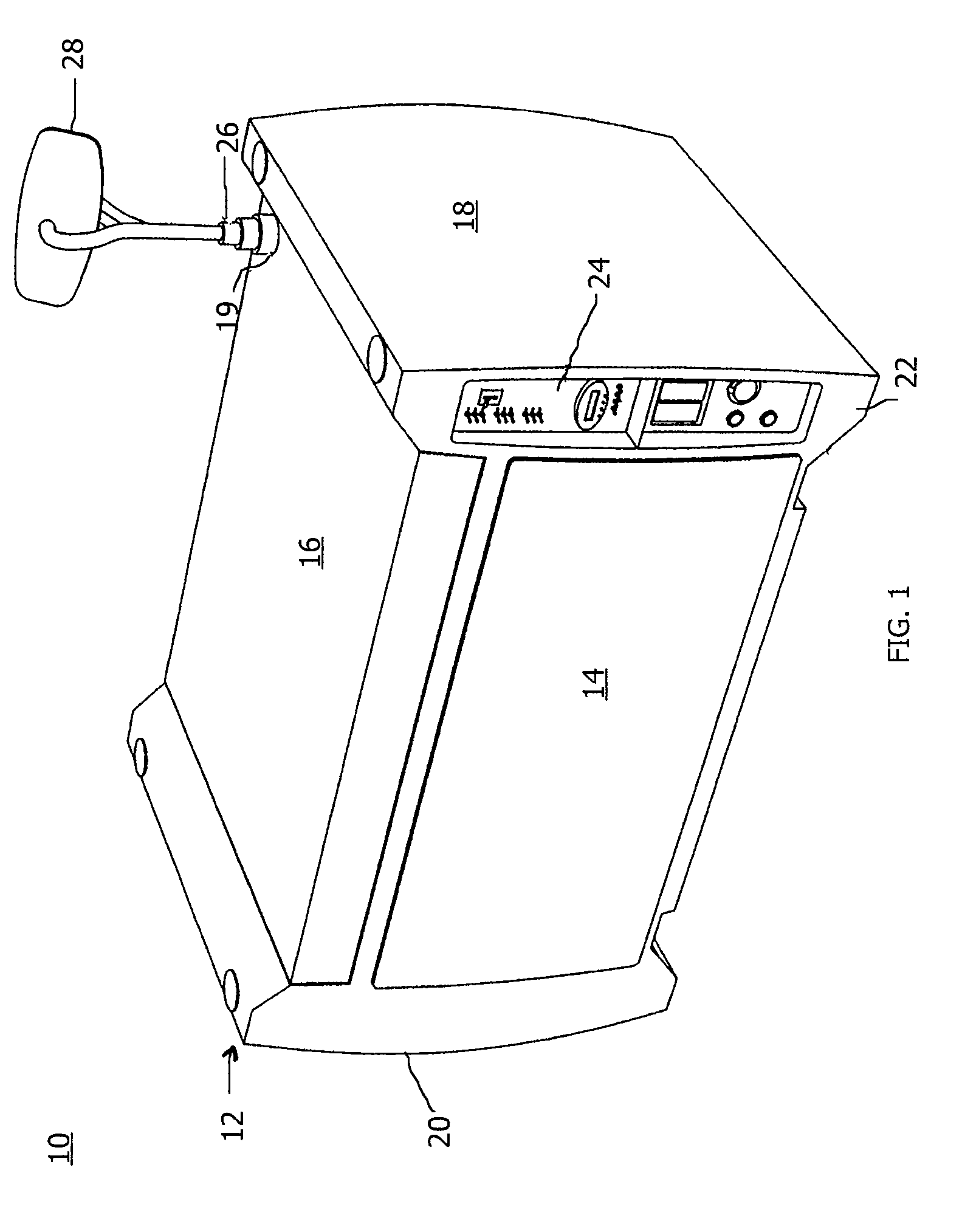
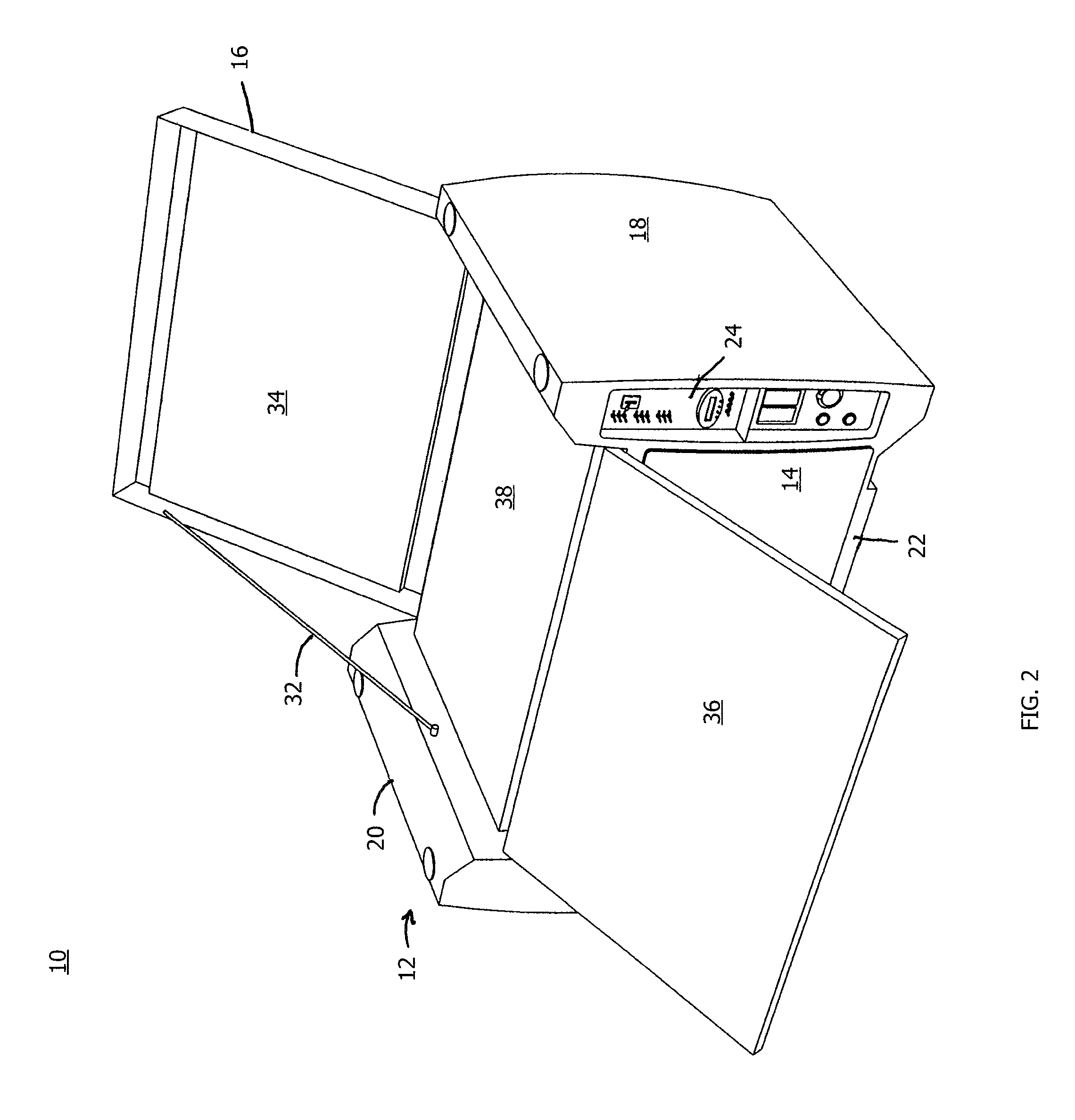
[0035]The present invention shown in FIG. 1 is a deployable power supply system 10 embodied in a housing 12 arranged for relative ease of movement and for storage of a plurality of components associated with power supply functionality at any selectable location. The housing 12 includes a front panel 14, a top panel 16, a first side section 18, and a second side section 20. The front panel 14 is removably attachable to a primary casing 22 and may be affixed to the primary casing 22 with attachment means, such as anti-theft attachment components, such as security bolting, for example. Anti-theft attachment components restrict access to devices within the housing 12 to authorized personnel only. The top panel 16 is hingedly or removably connected to the primary casing 22 to enable rotatable opening thereof. The first side section 18 includes a control panel 24 for management of power generation and distribution, and any other control functions of interest for the system 10. The first s...


PUM

PropertyMeasurementUnit
dimensionsaaaaaaaaaa
dimensionaaaaaaaaaa
energyaaaaaaaaaa

Abstract

A self-contained conveyable power unit for producing 12V / 24V, 110V AC, and 220V AC electricity at a desired location independent of external power sources integrates within one weather-resistant molded nonmetallic material based housing a power generating device of a selectable combination of a renewable energy type (e.g., solar), power management devices, power storage devices and management reporting devices. Additional optional power generating devices, renewable or of traditional fuel type, can be contained within or coupled to the housing. The system includes devices or an array of devices contained within the housing for the storage of electrical power. A device for power management is contained within the housing as is networking equipment of wireless or wired type for remote system observation and reporting. The system and housing are modular and configured to produce power using any combination of renewable and non-renewable energy resources. The conveyable power unit may provide easy access to different types of power outputs and inputs and be coupled with like appliances in a ‘daisy chain’ or network of power. Given its molded composite material construction and scaleable design, the appliance may be readily fabricated in a variety of sizes for varied applications. Further, the molded housing of composite material construction is designed for resistance to the elements, light weight and strength.

Description

BACKGROUND OF THE INVENTION[0001]1. Field of the Invention[0002]The present invention relates to self-contained power supply systems. More particularly, the present invention relates to systems that may be deployed to remote locations and that provide a self-contained power supply. Still more particularly, the present invention is a self-contained, conveyable energy conversion and storage device using ambient resources as the primary energy source. The system may include a plurality of power sources, including ambient power sources.[0003]2. Description of the Prior Art[0004]There are many instances in which portable power supplies are required, or at least preferred. In one instance, power may be required at a location where the primary power grid is not functioning, particularly where critical resources must be maintained. In another instance, power may be required at a location that is distant from any usable primary power grid, such as a remote location where no distribution infr...

Claims


Application Information

Patent Timeline
Patent Type & Authority Patents(United States)
IPC IPC(8): H01L31/045H01L31/048H01M50/209H01M50/222H01M50/271H01M50/296H02S30/20
CPCH01M2/1022H01M10/46H02S10/10H02S30/20H01M2250/30Y02B10/14Y02B90/18H02J7/355H02S10/40H02J7/35Y02E10/50Y02B10/10Y02B90/10Y02E60/50Y02E60/10H01M50/209H01M50/222H01M50/296H01M50/271
Inventor LYMAN, ZACHARYLYMAN, CABOTGENTENAAR, HENRY
Owner ZEROBASE ENERGY
Learn More