
Pipe coupling clamp

a coupling clamp and pipe technology, applied in the direction of flanged joints, fluid pressure sealed joints, sleeves/socket joints, etc., can solve the problems of two clamp halves disengaged, standard and well known clamps, and can be disengaged accidentally, so as to reduce the bearing surface and reduce the coupling strength. effect of clamp

Active Publication Date: 2011-02-08
ADVANCED COUPLINGS LTD
View PDF15 Cites 31 Cited by
  • Summary
  • Abstract
  • Description
  • Claims
  • Application Information

AI Technical Summary

Benefits of technology

The design ensures the clamp remains secure even if the nut loosens, preventing accidents and costly shutdowns, while the color coding aids in identifying hazardous materials, enhancing safety and operational efficiency.

Problems solved by technology

The joining of such pipes and the closing of such containers is not generally done with threaded connectors or closures because of the risk of contamination due to the use of threads.
Unfortunately, in certain instances, the standard and well known clamp, such as that described above, can be disengaged accidentally, for example, by somebody brushing against the nut which is usually a wing nut.
Unfortunately, after the wing nut is loosened, then the whole eyebolt can pivot outwards and thus cause the two clamp halves to disengage.
The problem is if, for example, the pipes are transporting corrosive or very hot liquids, serious injuries can occur.
However, the problem arises when the clamp totally disengages and then there can be serious consequences.
A further problem is to prevent unauthorised personnel from opening such closures or indeed disengaging such pipe ends.
Furthermore, due to the nut associated with such clamps unscrewing over time, or as a result of mishaps during installation of clamps, it is possible for the nut to accidentally become separated from the clamp, which may result in it being accidentally dropped into a vessel or an un-sanitised area of a plant room.
This will normally result in costly “shut down” times. Further problems arise in relation to the use of pipes coupled by such clamps, as it is difficult for maintenance engineers to identify hazardous materials which the pipes coupled by the clamps are transporting.
These prior art configurations for clamps are however complex arrangements which are difficult to cleanly finish and are possibly not totally safe.

Method used


Image

  • Pipe coupling clamp
  • Pipe coupling clamp
  • Pipe coupling clamp

Examples


Embodiment Construction

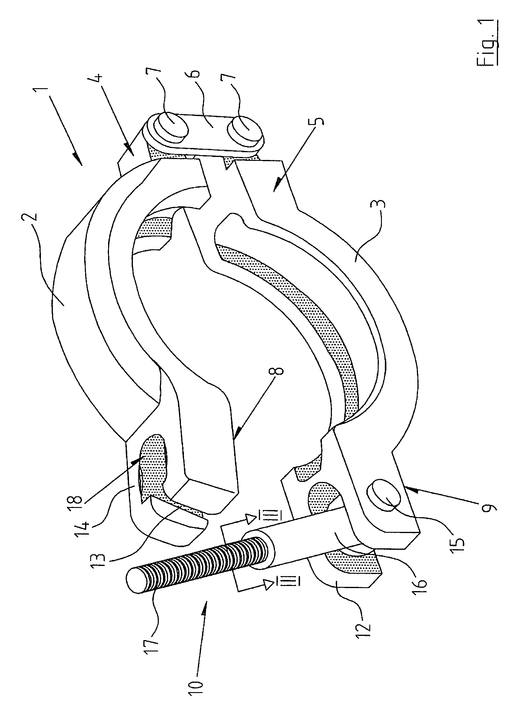
The invention will be more clearly understood from the following description of some embodiments thereof, given by way of example only, with reference to the accompanying drawings, in which:

FIG. 1 is a perspective view, partially disassembled, of a pipe coupling clamp according to the invention,

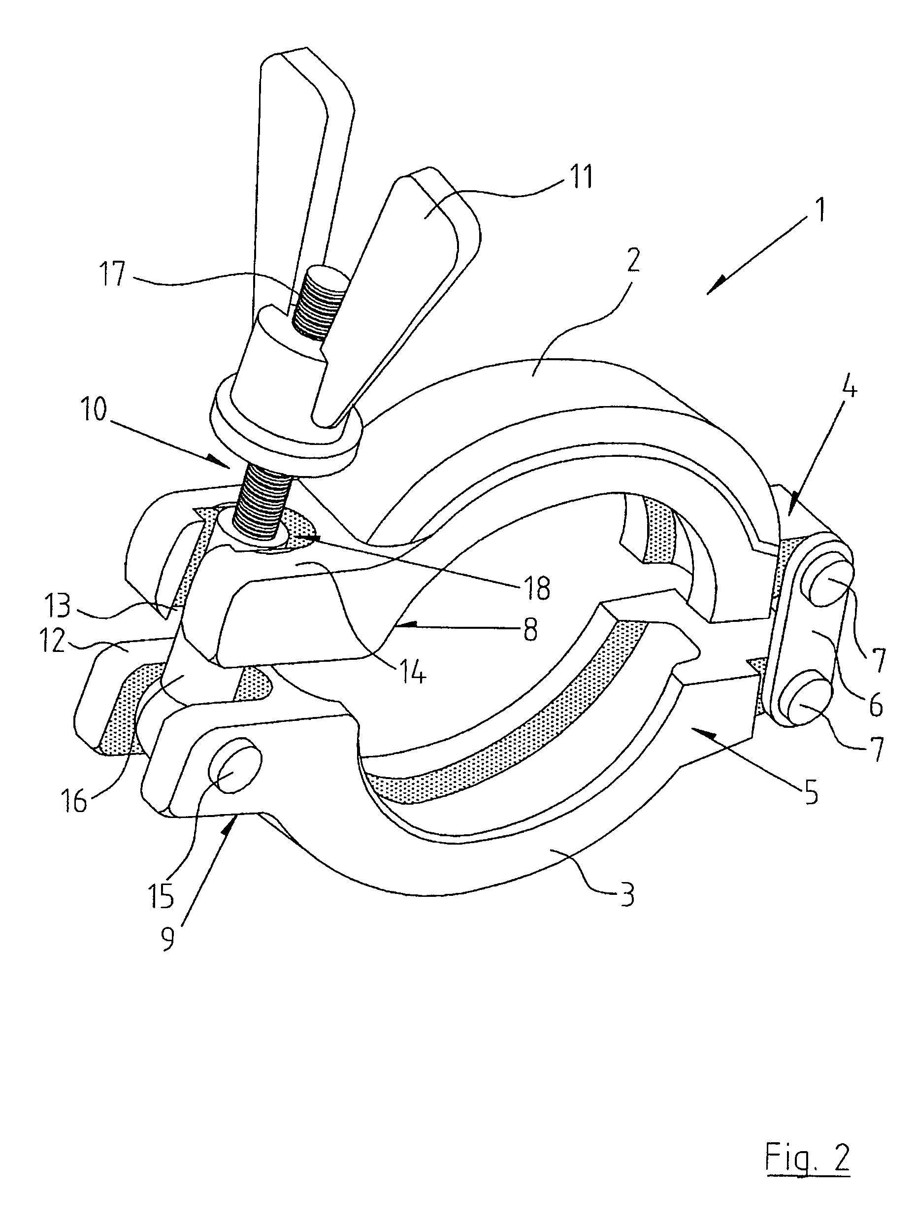
FIG. 2 is a perspective view showing the clamp about to be closed,

FIG. 3 is a sectional view in the direction of the arrows III-III of FIG. 1,

FIG. 4 is a sectional view of the pipe coupling clamp shown in FIG. 2,

FIG. 5 is a sectional view of a wing-nut used in conjunction with the pipe coupling clamp shown in FIGS. 1 to 4,

FIG. 6 is a sectional view similar to FIG. 3 of an alternative construction of clamp according to the invention,

FIG. 7 is an exploded view of a still further pipe coupling clamp according to the invention,

FIG. 8 is a perspective view of the assembled pipe coupling clamp of FIG. 7,

FIG. 9 is a perspective view of a still further pipe coupling clamp, partially disassembled, acc...


PUM


Abstract

A pipe coupling clamp including a pair of clamp half members essentially C-shaped in cross-section each having a pipe flange receiving groove for receiving the mating flanges of two pipes to be coupled. The clamp half members being hinged together at one pair of ends by a hinge including plates and releasably connected together at the other pair of ends by a locking eyebolt and associated locking eyebolt nut hingedly connected at its proximal end to the end of one clamp half member to allow pivoting moving through a slot into an open securing jaw on the other end. The locking eyebolt includes, at its proximal end, an eyebolt seating portion connected to a stepped threaded portion of reduced diameter at its distal end. Thus, initially, on loosening of the nut, the locking eyebolt will not disengage from within the securing jaw.

Description

The present invention relates to a pipe coupling clamp comprising a pair of clamp halves substantially C-shaped in cross-section, and grooved to receive mating flanges of two pipes to be coupled, the clamp halves being hinged together at one pair of ends and releasably connected together at the other pair of ends by a locking eyebolt and associated nut, which locking eyebolt is hingedly connected at its proximal end within an open support jaw on the end of one clamp to allow it to pivot through a receiving slot which is connected to an open securing jaw on the end of the other clamp half.In the pharmaceutical and food industries, it is a requirement that liquids be transported, stored and processed in sanitary conditions. It is common to use stainless steel pipes and containers with closures. The joining of such pipes and the closing of such containers is not generally done with threaded connectors or closures because of the risk of contamination due to the use of threads. Many stai...

Claims


Application Information

Patent Timeline
Patent Type & Authority Patents(United States)
IPC IPC(8): F16L23/00
CPCF16L23/10
Inventor HENRY
Owner ADVANCED COUPLINGS LTD
Learn More