
System and method for generating and directing very loud sounds

a sound and loud technology, applied in the field of system and method for producing and directing loud sound, can solve the problem of varying the sound level of the projector

Active Publication Date: 2011-02-08
SOUNDBLAST TECH
View PDF36 Cites 41 Cited by
  • Summary
  • Abstract
  • Description
  • Claims
  • Application Information

AI Technical Summary

Benefits of technology

[0020]The invention provides a method for producing a sound wave including the steps of supplying a fuel-oxidant mixture to at least one detonator having at least one spark initiator where the fuel-oxidant mixture flows through the at least one detonator and into the closed end of at least one detonation tube also having an open end, and controlling the timing of the at least one spark initiator to initiate at least one spark within the at least one detonator while the fuel-oxidant mixture is flowing through the at least one detonator thereby initiating a detonation wave at the closed end of the at least one detonation tube where the detonation wave propagates the length of the at least one detonation tube and exits the open end of the at least one detonation tube as a sound wave.

Problems solved by technology

These sound levels that can be projected may vary from annoying at the low end, disabling at the mid range and lethal at the high end.

Method used


Image

  • System and method for generating and directing very loud sounds
  • System and method for generating and directing very loud sounds
  • System and method for generating and directing very loud sounds

Examples


first embodiment

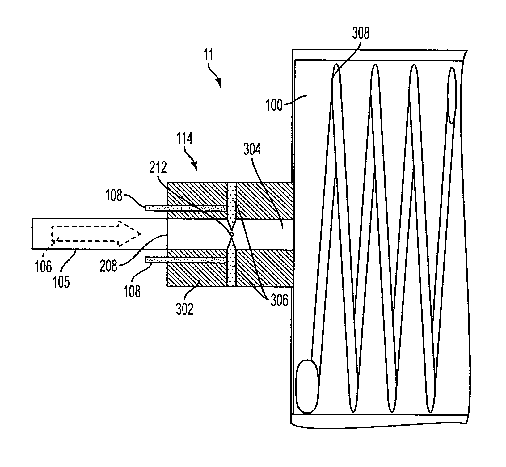
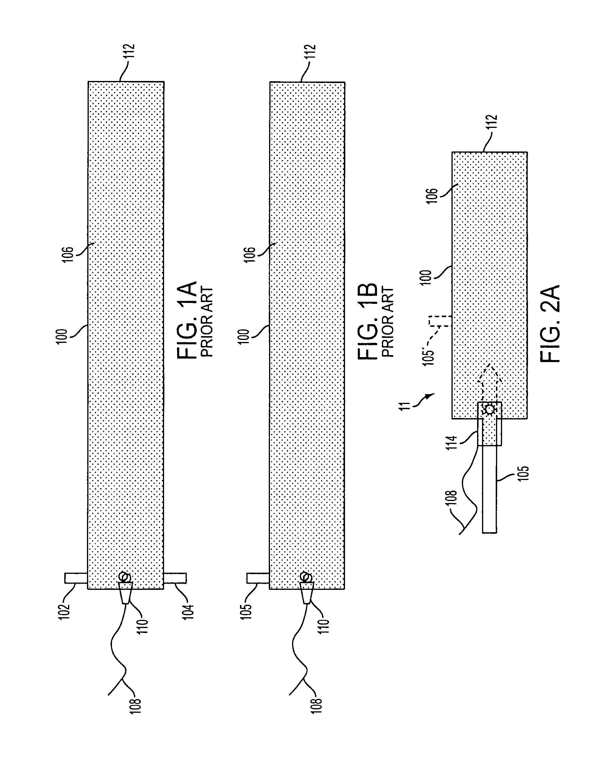
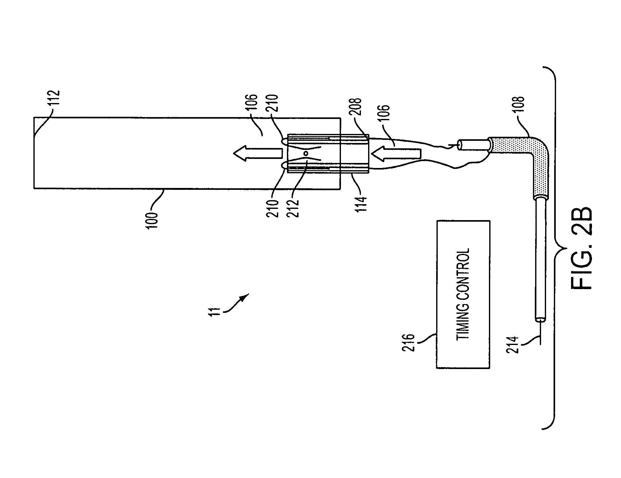
[0068]FIG. 2B depicts the detonator of the present invention that functions by creating an electrical arc within a stream of a detonatable gas mixture. As shown in FIG. 2B, a gas mixture 106 of a combustible gas and oxidizer in the correct detonable ratio is passed into a detonation tube 100 via fill point 208 of detonator 114. When the tube is substantially full, high voltage wire 108 is triggered at high voltage trigger input 214 to cause a spark 212 to occur across bare wires 210 and to pass through the gas mixture 106 flowing into the detonation tube 100 to initiate detonation of the gas in the detonation tube 100. Triggering of high voltage trigger is controlled by timing control mechanism 216.

second embodiment

[0069]FIG. 2C depicts the detonator of the present invention that also functions by creating an electrical arc within a stream of a detonatable gas mixture. As shown in FIG. 2C, a gas mixture 106 of a combustible gas and oxidizer in the correct detonable ratio is passed into a detonation tube 100 via fill point 208 of detonator 114. When the tube is substantially full, high voltage wire 108 is triggered at high voltage trigger input 214 to cause a spark 212 to occur across bare wires 210 and to pass through the gas mixture 106 flowing into the detonation tube 100 to initiate detonation of the gas in the detonation tube 100. In this variation the spark is initiated within detonator 114 and then it is quickly swept along the two diverging conductors into the detonation tube 100 by the flowing gas, the length of the spark increasing as it travels into the detonation tube 100. When a spark is initiated in a small gap it creates a stable low impedance zone that is capable of conducting t...


PUM


Abstract

An improved system and method for controlling and directing sound waves is provided. A fuel-oxidant mixture is supplied to at least one detonator having at least one spark initiator. The fuel-oxidant mixture flows through the at least one detonator and into the closed end of at least one detonation tube also having an open end. The timing at least one spark initiator is controlled to initiate at least one spark within the at least one detonator while the fuel-oxidant mixture is flowing through the at least one detonator thereby initiating a detonation wave at the closed end of the at least one detonation tube. The detonation wave propagates the length of the at least one detonation tube and exits the open end of the at least one detonation tube as a sound wave. When multiple detonation tubes are detonated with controlled timing, the resulting sound waves are directed to a desired location. Sound waves can be directed from groups of detonation tubes and from a sparse array of detonation tubes.

Description

CROSS REFERENCE TO RELATED APPLICATIONS[0001]This application claims priority to U.S. Provisional Patent Application 60 / 792,420, filed Apr. 17, 2006, and U.S. Provisional Patent Application 60 / 850,683, filed Oct. 10, 2006, both of which are incorporated herein by reference.FIELD OF THE INVENTION[0002]The present invention relates generally to a system and method for producing and directing sound loud enough to be used as a weapon. More particularly, the present invention relates to a method of using partially confined gas detonation to produce and direct very loud sound waves toward people, structures or animals for use as a weapon.BACKGROUND OF THE INVENTION[0003]In the process of conducting warfare in urban settings it is often desired to employ a weapon that causes limited or no damage to people and / or structures. The arsenal available to a typical fighting force however was designed for all out war and as a consequence was designed to produce the maximum lethality and property d...

Claims


Application Information

Patent Timeline
Patent Type & Authority Patents(United States)
IPC IPC(8): G01V1/06
CPCF41H11/12F41H11/16F41H13/0081F42D5/04F41A33/04
Inventor FULLERTON, LARRY W.
Owner SOUNDBLAST TECH
Learn More